V
Hello! I have followed you since the beginning of the project, I am interested in the dedicated board, to be able to connect sensors When will it be available? Greetings, you have done a great job!

The complete instructions below adapt to your ESP32 board.
Build the original FoxLAP GPS lap timer with an ESP32-WROOM-32, a 256×128 SPI display, a u-blox GNSS receiver, microSD recording and a rechargeable 18650 battery.
This FoxLAP DIY tutorial has continued to evolve since its first publication in late 2021. The instructions have been updated while preserving the original ESP-32 Dev Kit C V4 build. For reliable GNSS reception, this tutorial uses the proven MatekSYS SAM-M10Q, which remains fully supported and works perfectly with FoxLAP DIY.
At the end of this tutorial, you will have a fully functional GPS lap timer.


It does, however, come with a few limitations. This DIY version is intentionally focused on the essential GPS lap-timing functions. It is not designed to be fully water-resistant and uses a simple physical power switch instead of an advanced battery-management system.
And yes, the inside is going to look a little rough, with hand-soldered wires and hot glue!
This is intentionally a quick and simple implementation. The first FoxLAP prototype was built in almost exactly the same way so that I could start developing the firmware. I rebuilt one for this tutorial without spending too much time trying to make the internal assembly perfect. I’m sure many of you can build something cleaner — and if you do, please share it!
Despite these limitations, you still get the essential FoxLAP features: lap timing, gap to best lap, speed, sectors, theoretical best lap, live delta and session recording. You can also analyse your recorded GPS data afterwards using GPXRender software or with the online tool
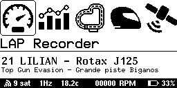
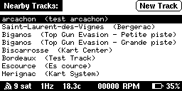
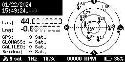
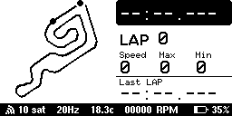
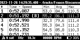
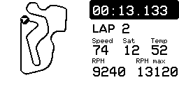
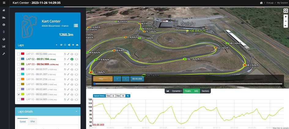
The goal of this tutorial
The aim is to build the simplest possible FoxLAP device using readily available components. This is very close to the hardware i originally used when I started developing FoxLAP, so rebuilding it for this tutorial brings back a few memories
Is it the ultimate hardware design? Definitely not. Could some components be replaced with better or cheaper alternatives? Of course.
Why Blender? Why this display? Why this ESP32 board? There are plenty of choices that could be debated or improved. But this version exists, it works, and it is relatively easy to reproduce.
So, ready to build one?
This is what I used, mainly because I already had most of these items at home. Some of these parts can be replaced with more convenient or cheaper alternatives, depending on what is available in your country.
I have included links to purchase the components, but I have no affiliation with these sellers and I do not earn anything from these links. You are of course free to buy the parts wherever you prefer.
More & important informations:
1- GNSS module: this tutorial is designed to use the MatekSYS SAM-M10Q mounted inside the enclosure. However, you can probably use any genuine u-blox GNSS module. Please avoid very cheap GNSS replicas. A $5 GNSS module is unlikely to provide the accuracy and reliability you want for lap timing. You can find cheaper genuine u-blox modules such as the M8N, but you will be limited to 10 Hz. That is still perfectly usable — for comparison, the Alfano 6 GNSS also runs at 10 Hz. With some M8N modules, you may not be able to install the GNSS receiver inside the enclosure, so it will have to remain external. In that case, you will need to adapt the 3D enclosure model. I already have a few 3D models designed for this type of configuration.
I had good results with this u-blox M8N receiver:
https://www.aliexpress.com/item/32748573256.html
At the moment, this project is only compatible with u-blox GNSS chips. I may add support for other GNSS modules in the future if they prove to be reliable, accurate and affordable. Some users have also successfully used the QUESCAN M10Q.
Note: on first startup, FoxLAP attempts to communicate with the GNSS receiver at 9600 baud. Depending on the module you use, you may therefore need to configure the GNSS receiver before installing it.
2- Display: this JLX 256×128 COG is available in both 5 V and 3.3 V versions. I used the 5 V version simply because I already had one. The battery shield used in this tutorial includes a 5 V boost converter, so I used it to power the ESP32, the GNSS module and the display. You can also use the 3.3 V version of the display, but obviously do not connect it directly to 5 V. I chose the white backlight version simply because I prefer white backlights.
Important: the display must be the SPI version.
3- MicroSD card: the ESP32 cannot directly use FAT32 partitions larger than 32 GB, so I recommend using a card of 32 GB or less. If you use a larger card, you will first need to create a 32 GB FAT32 partition on it. For this project, even 16 GB is already more than enough. As with the GNSS module, avoid cheap no-name microSD cards. They can cause all kinds of read/write errors and intermittent problems that are extremely frustrating to diagnose. I have already wasted far too much time with cheap cards before eventually throwing them in the trash! Use a reputable brand and save yourself the headache.
4- 18650 battery: again, don’t be fooled by unrealistic specifications. Avoid no-name batteries advertised as 12,000 mAh or similarly impossible capacities. Use a good-quality 18650 cell from a reputable manufacturer. The battery’s positive and negative terminals must be flat.
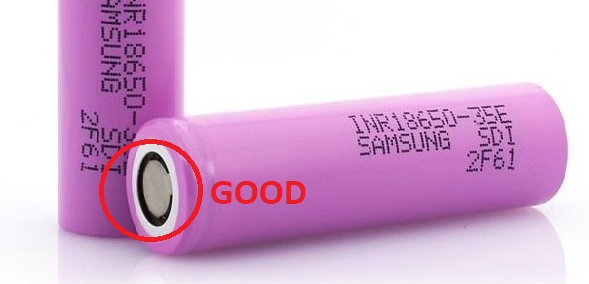
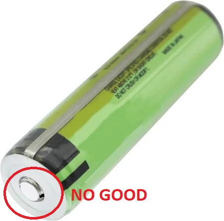
With batteries that have a raised button-top terminal, it may be difficult or even impossible to fit the battery into the slot provided in the enclosure.
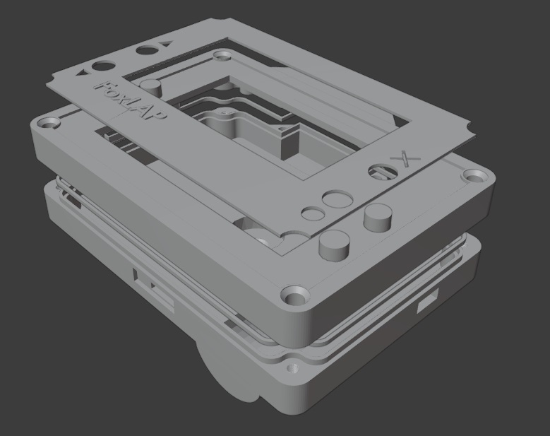
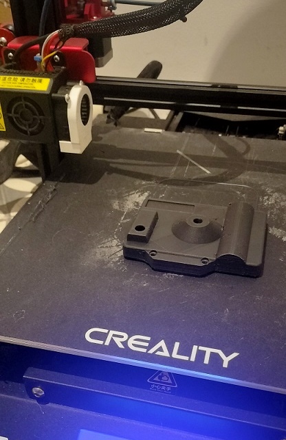
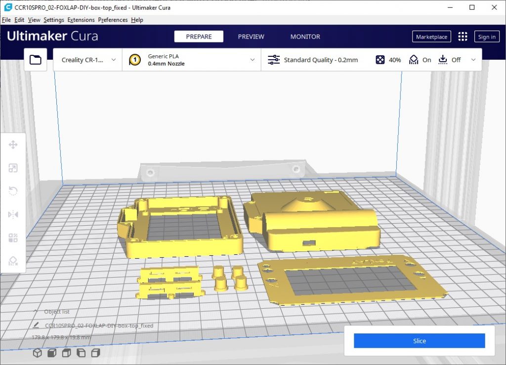
I’m not a 3D-printing expert, but I got my best results by printing the STL models this way. In the screenshot, I assembled all the STL parts together only to show you how they are positioned. In practice, I printed each STL part separately, not all together as shown in the image.
There is also 2 other parts printed with flexibale filament. You will need two M8 flat-washer parts. They will help you mount the lap timer securely to the steering wheel. This filament gives very good results, but it is quite expensive, and you probably won’t want to buy an entire spool just for two small parts. You can try printing them with regular PLA instead.
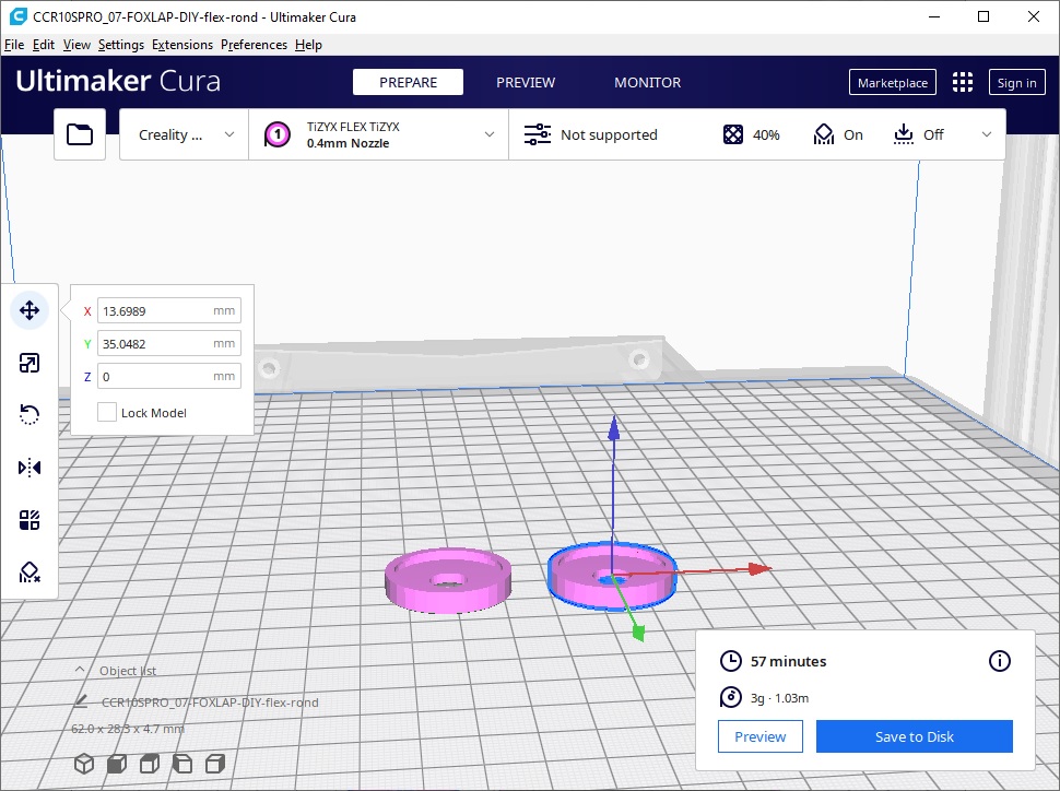
Here is the STL files you must print:
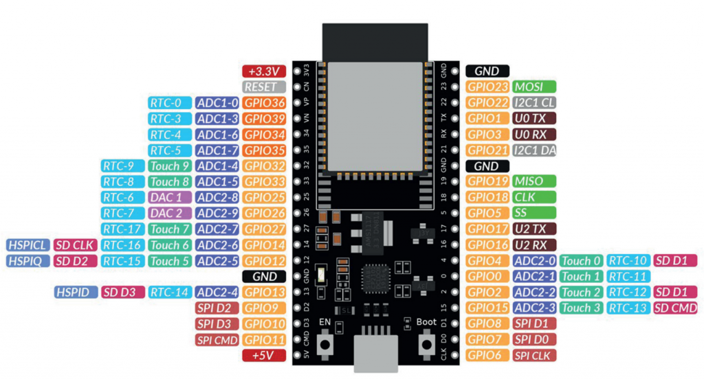
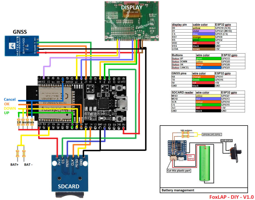
From this point on, you should have the 3D-printed enclosure and all the electronic components in front of you. Here is the complete wiring diagram. Even though the circuit itself is quite simple, it requires a fairly large number of wires.
Choose a component to display every connection. The GPIO numbers below match the original FoxLAP DIY wiring diagram.
| Display pin | Cable color | ESP32 pin | Function |
|---|---|---|---|
| D0 | Yellow | GPIO18 | SPI clock (SCK) |
| D1 | Violet | GPIO23 | SPI data (MOSI) |
| CS | Blue | GPIO5 | Chip select |
| RST | Orange | GPIO0 | Display reset |
| RS | Green | GPIO2 | Command/data selection (DC in firmware) |
| VDD | Red | 5V | Display supply |
| VSS | Black | GND | Ground |
| LEDA | Brown | 5V | Backlight supply |
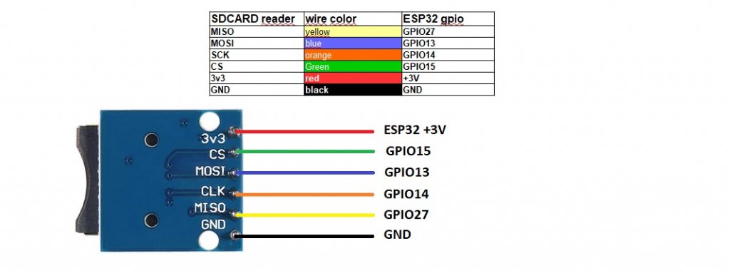
| microSD pin | Cable color | ESP32 pin | Function |
|---|---|---|---|
| MISO | Yellow | GPIO27 | SPI data from microSD |
| MOSI | Blue | GPIO13 | SPI data to microSD |
| SCK / CLK | Orange | GPIO14 | SPI clock |
| CS | Green | GPIO15 | Chip select |
| 3V3 | Red | 3V3 | Module supply |
| GND | Black | GND | Ground |
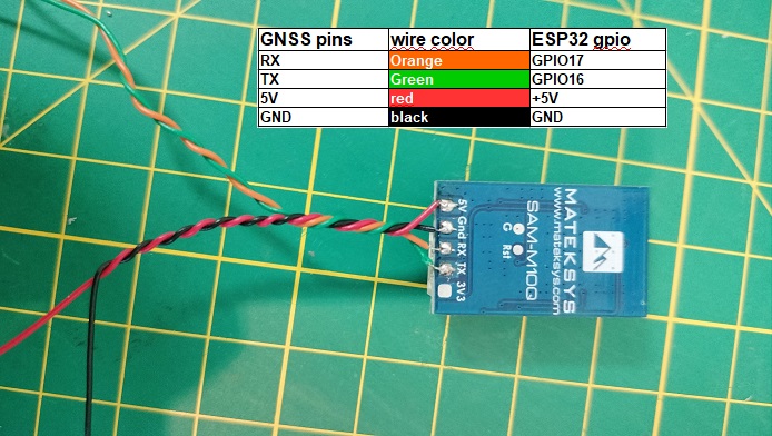
| GNSS pin | Cable color | ESP32 pin | Connection |
|---|---|---|---|
| RX | Orange | GPIO17 | ESP32 TX2 → GNSS RX |
| TX | Green | GPIO16 | GNSS TX → ESP32 RX2 |
| 5V | Red | 5V | GNSS supply |
| GND | Black | GND | Ground |
| WS2812B LED bar | ESP32 connection | Notes |
|---|---|---|
| DIN / Data in | GPIO12 | Firmware LED control signal |
| +5V | 5V | Regulated 5 V supply |
| GND | GND | Common ground with FoxLAP |
| Function | ESP32 pin | Connection |
|---|---|---|
| Main supply | 5V | 5 V output from the lithium battery charger board |
| Common return | GND | Common ground for every module |
| Battery measurement | GPIO36 / VP | Midpoint of two 10 kΩ resistors across the battery |
3.1 Buttons assembly
Insert the four buttons into the button holder you printed earlier.
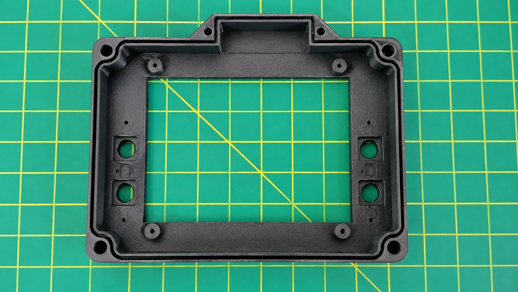
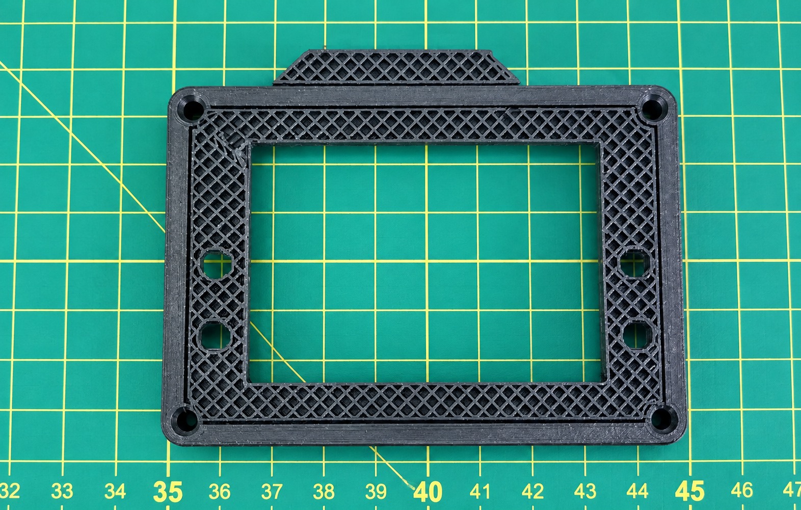
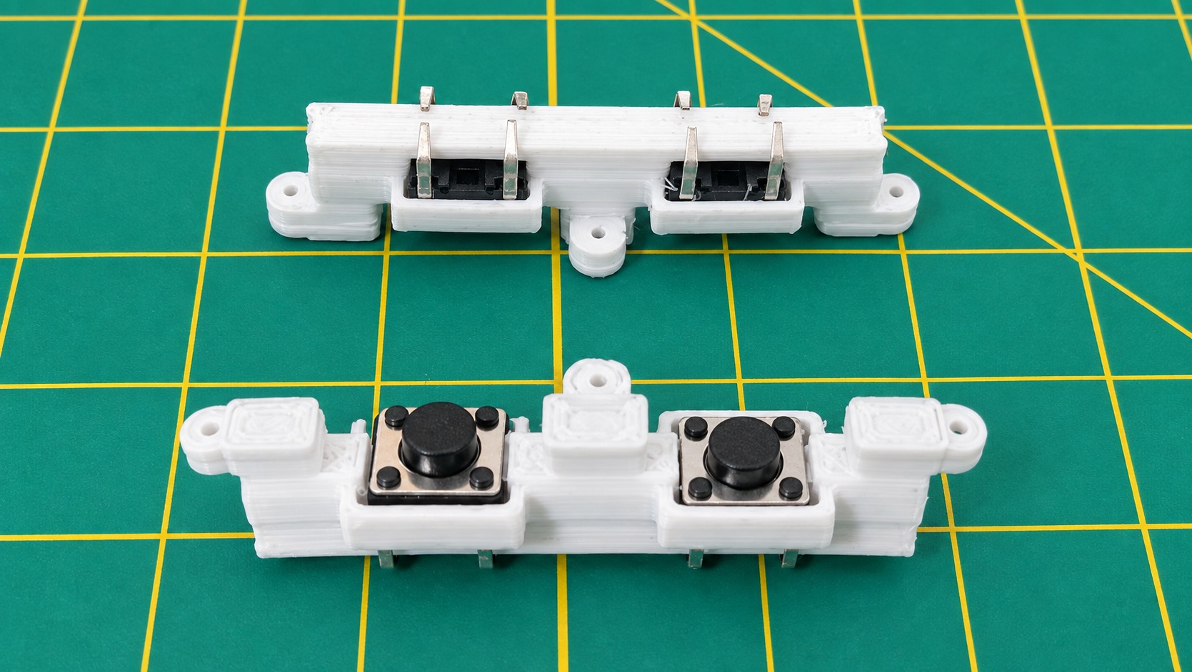
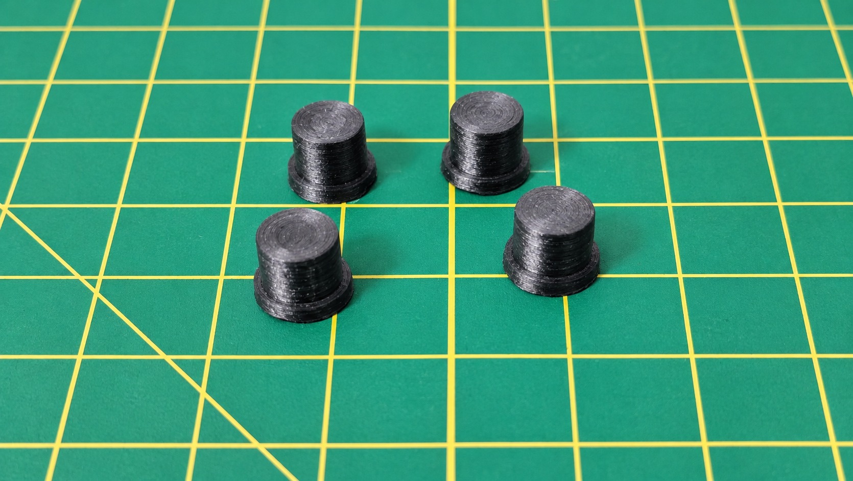
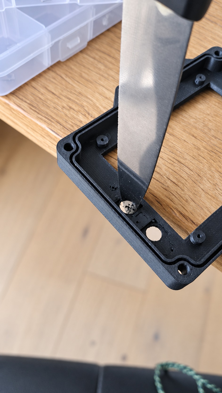
Make sure the buttons slide freely without binding. Enlarge the holes slightly if necessary, as 3D printing can sometimes leave a small amount of excess material around the edges.
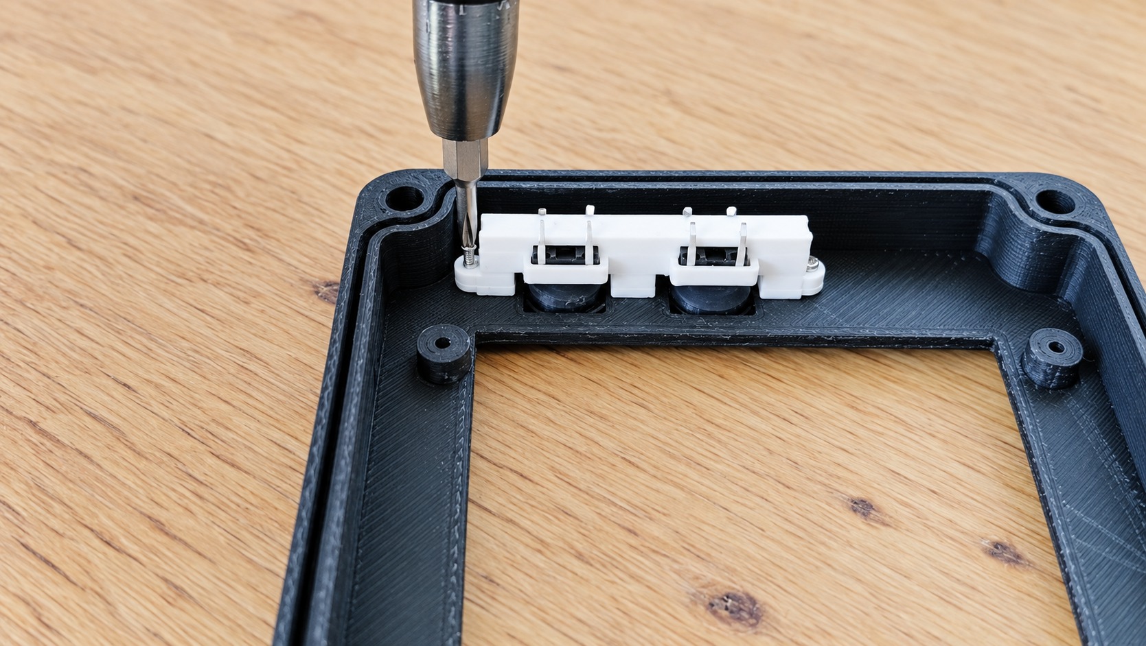
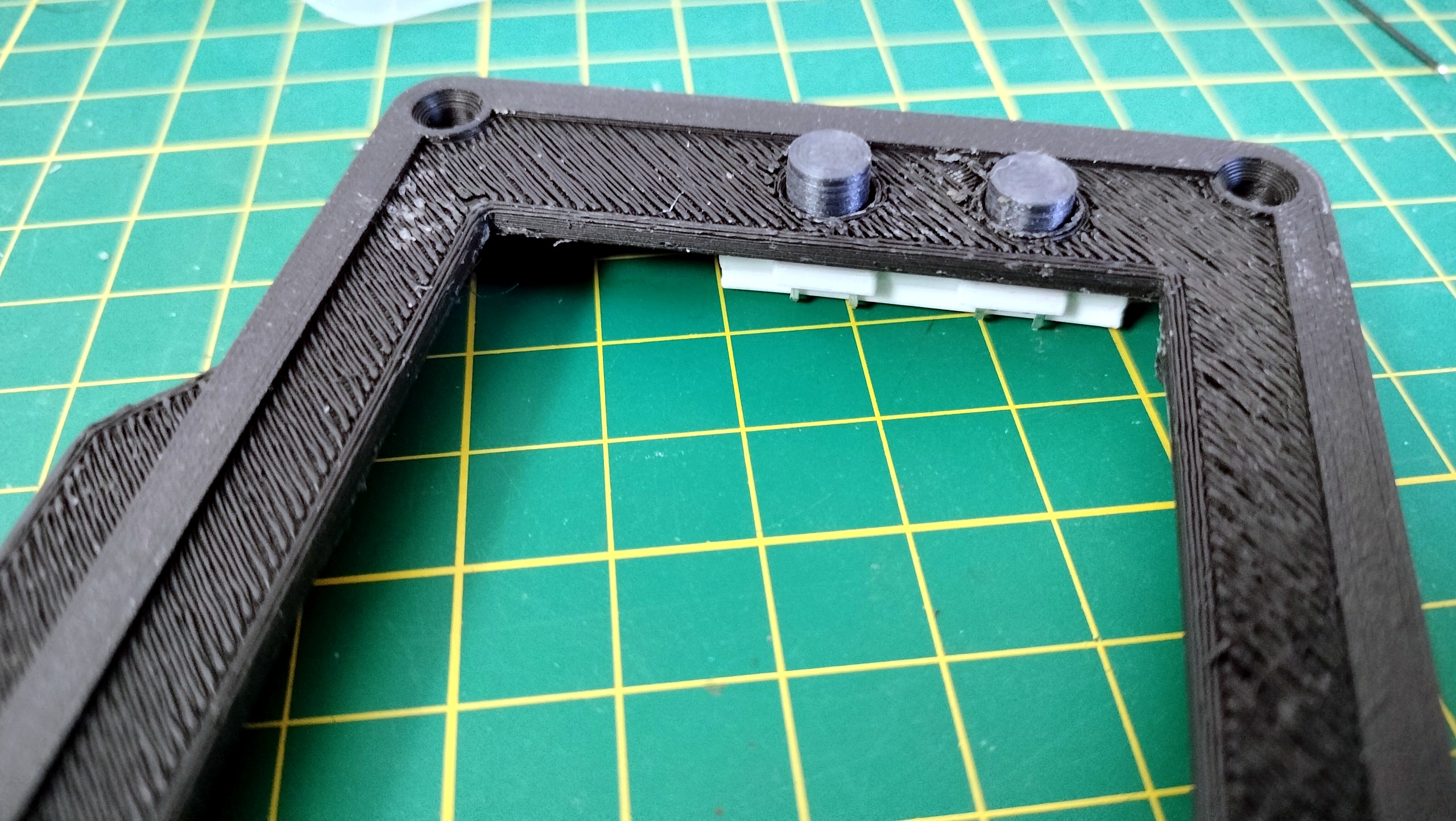
Then attach the button-holder parts using M1.2 × 5 mm screws. Repeat the same process for both the left and right button assemblies.
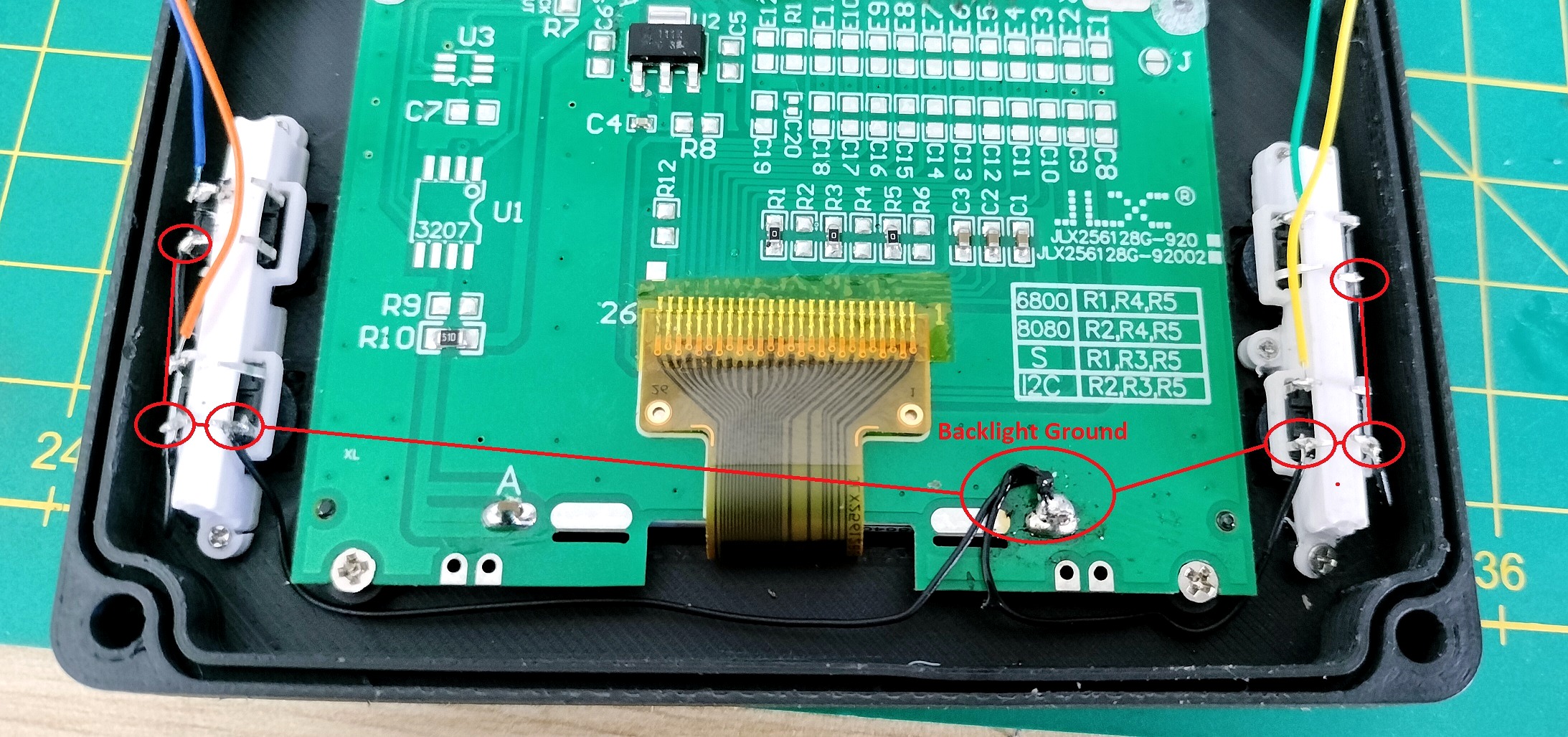
Connect all the button ground pins together, then connect them to the display’s K ground pin. Use a different wire color for each button. This will make it much easier to identify the correct wire when you solder them to their corresponding ESP32 GPIO pins later. It’s time to add the 4 debounce resistors on the buttons.
IMPORTANT: you may not have to add the debounce resistors (even if it’s not recommanded). But you must add them if you are willing to use the device in engine environnement
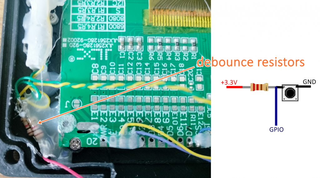
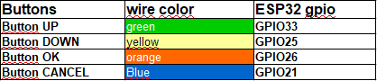
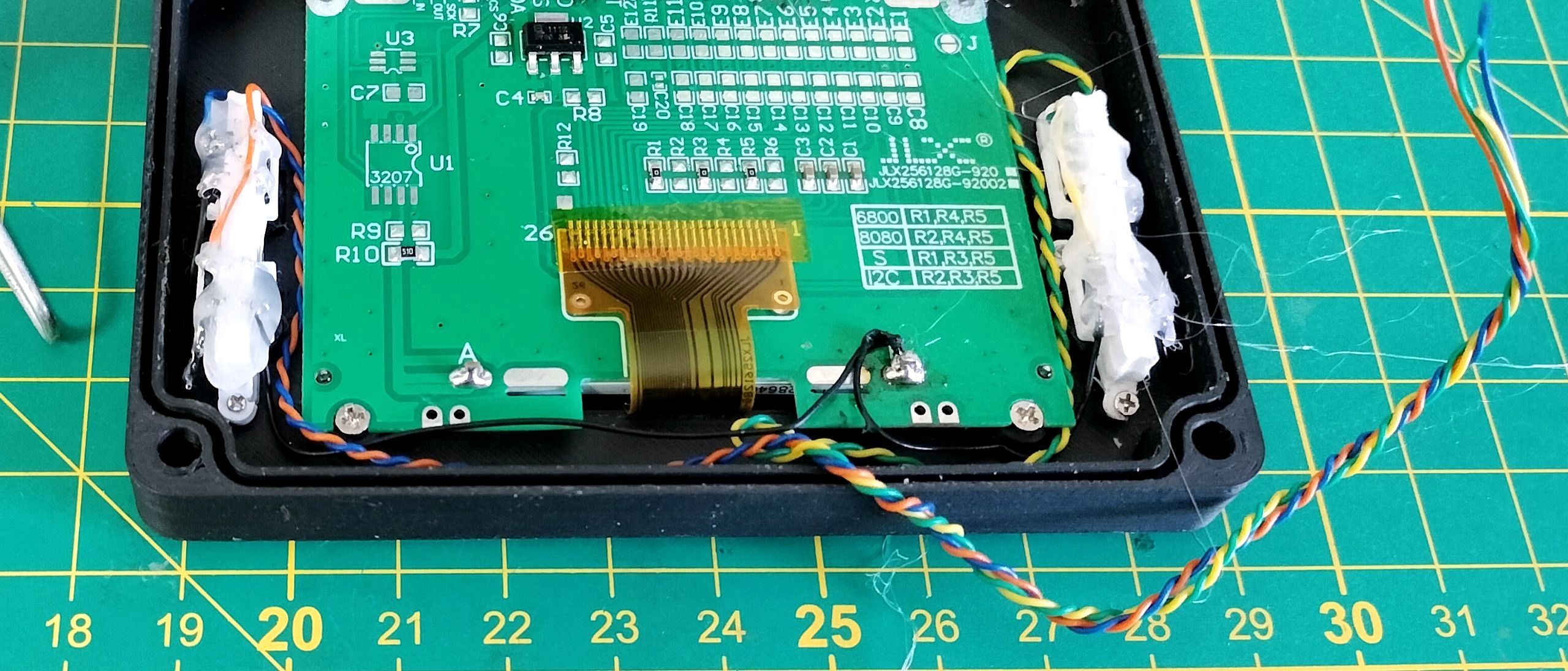
Apply hot glue to all solder joints. Remember: vibration is our enemy. Leave enough length on the wires, as you will need to solder them later to the ESP32 located in the other half of the enclosure.
3.2 Display assembly
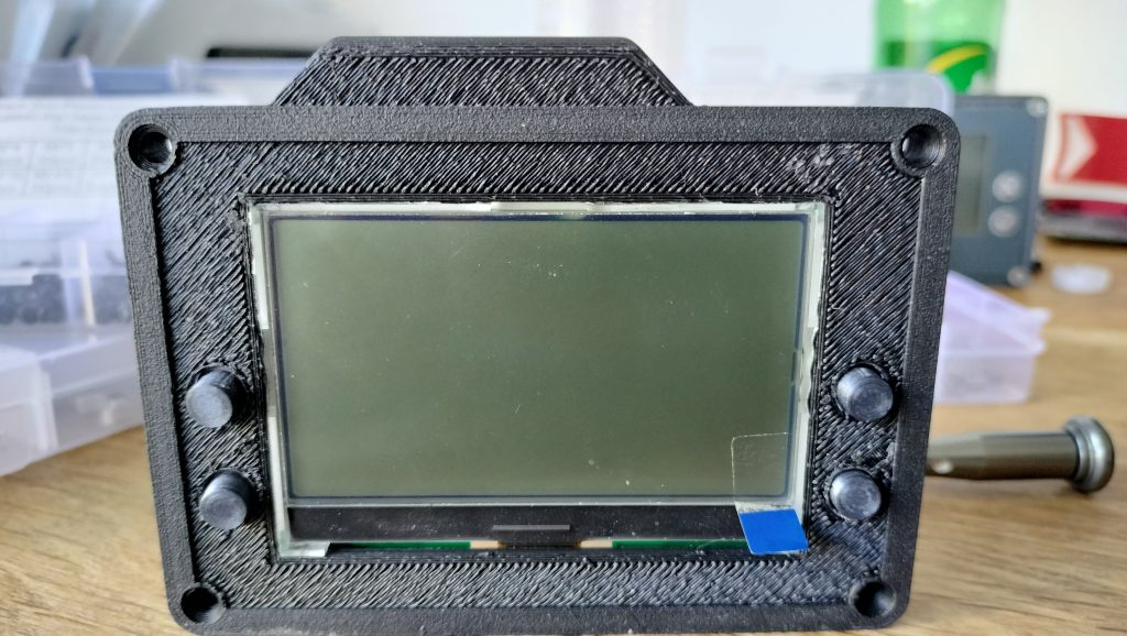
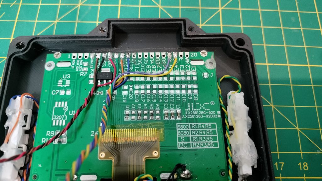
Install the display and secure it with the screws. You can add a small amount of hot glue to help position the display correctly and make sure it does not move.
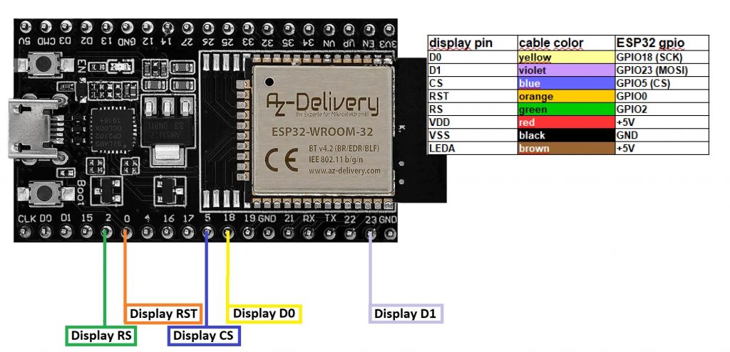
Here is how the display should be connected to the ESP32. Prepare and solder the wires to the display, but do not solder them to the ESP32 yet. Again, leave enough length on the wires, as you will need to connect them later to the ESP32 located in the other half of the enclosure.
3.3 Bottom part assembly
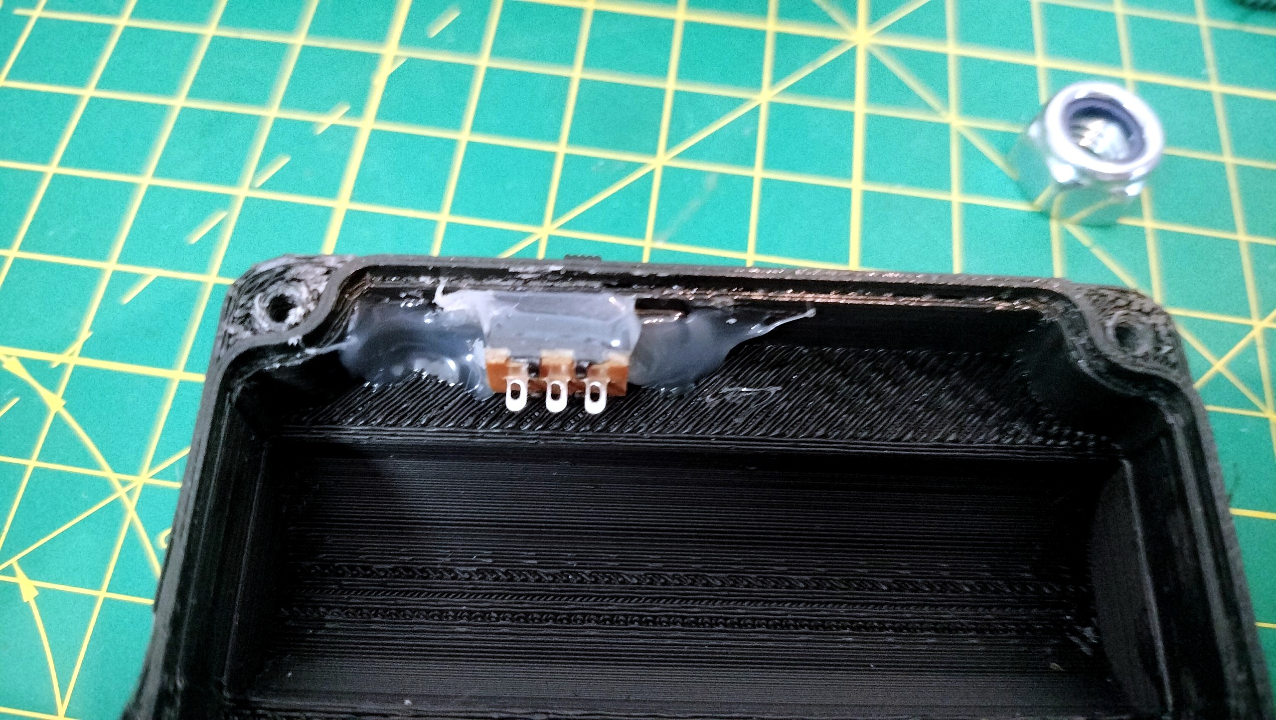
Place the power on/off switch and hot glue it.
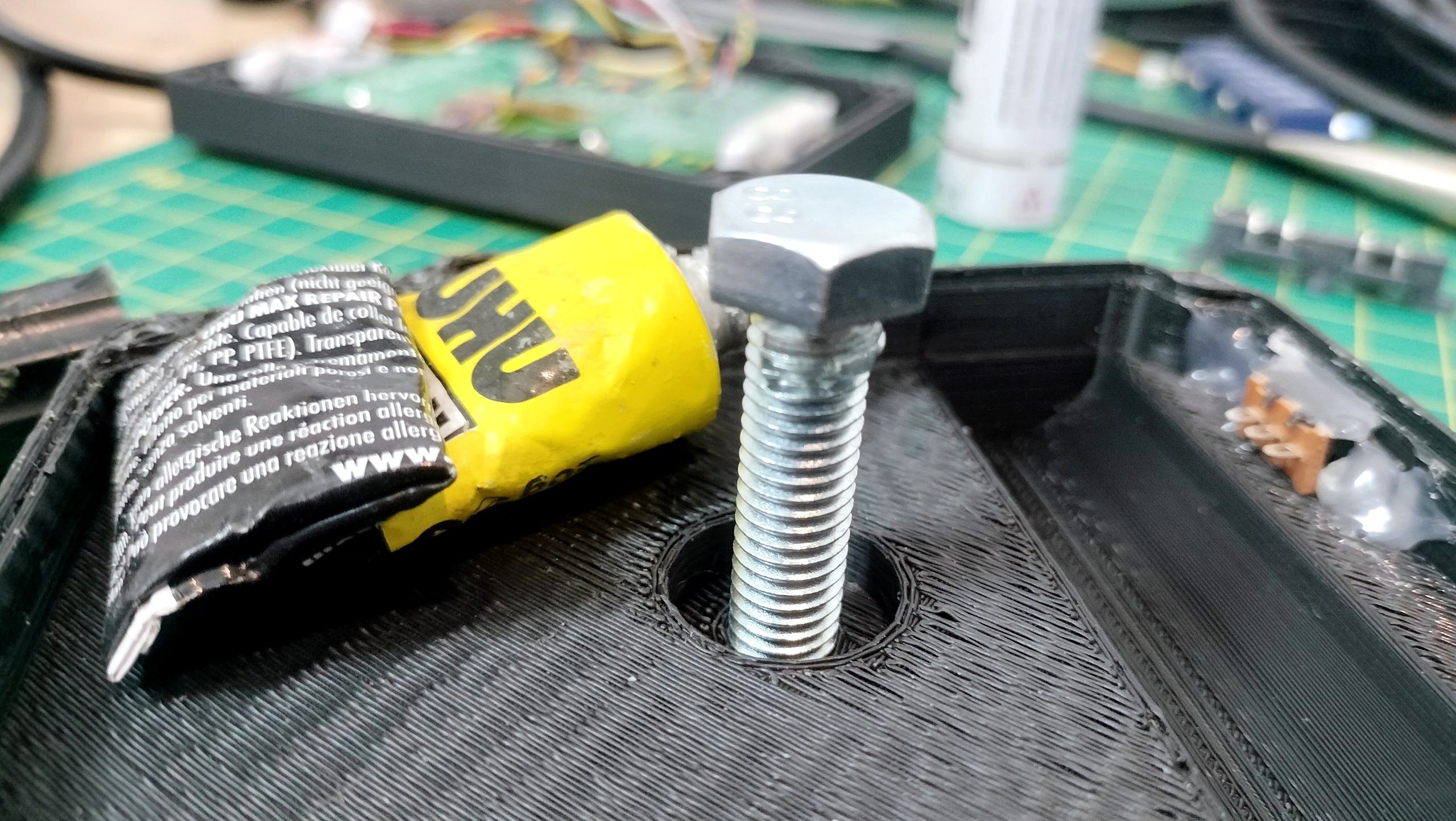
Insert the M8 × 30 mm screw, apply a small amount of regular glue to the top of the screw, then tighten it into place.
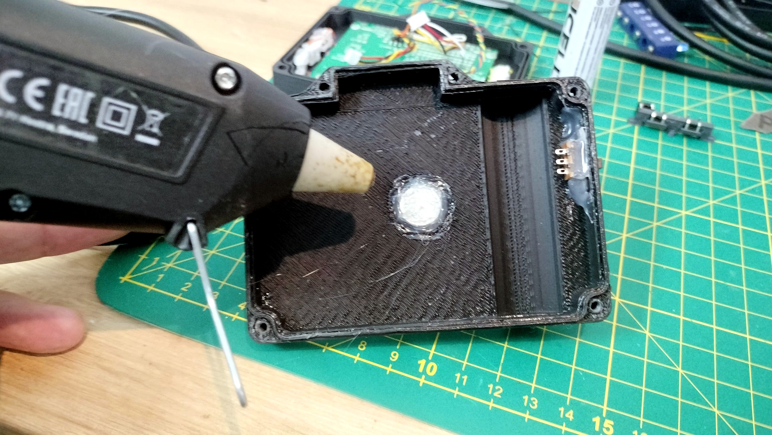
Fill the remaining space around the M8 screw head with hot glue to secure it firmly in place.
3.4 Battery assembly
Now take your 18650 battery and use a spot welder to attach nickel strips to both terminals.
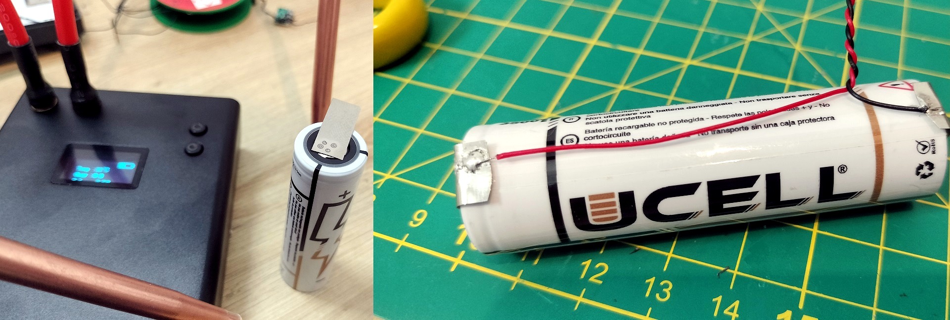
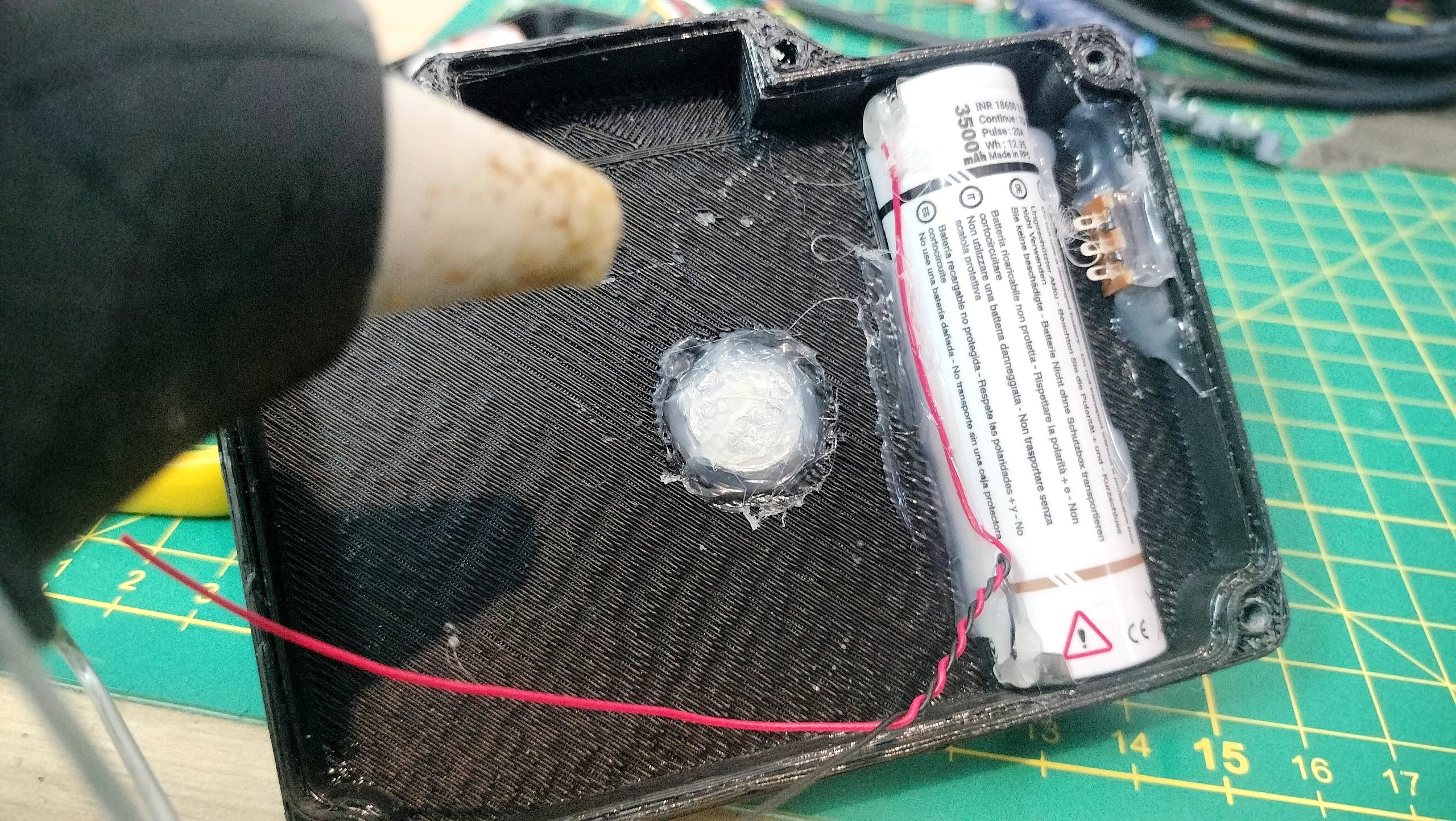
Place the battery inside the enclosure and apply hot glue around it to hold it securely in place.
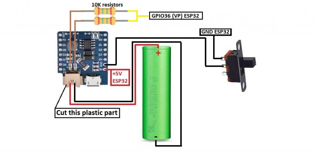
Follow this wiring diagram to connect the lithium battery charger
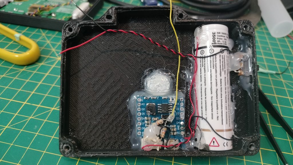
You should now have something that looks like this.
Make sure the power switch is OFF during the following steps.
At this point, you can also check that the battery charges correctly and verify that you can measure approximately +5 V between the 5V and GND pins on the lithium battery charger board. The two 10 kΩ resistors connected across the battery terminals will allow us to estimate the battery level using the ESP32 ADC. This is clearly not the most accurate way to measure battery level, but remember: this tutorial is intended to build a simple and inexpensive version of FoxLAP. It will still give you a reasonable indication of the remaining battery level.
3.5 GNSS assembly
Take your MatekSYS SAM-M10Q GNSS module. Prepare the required wires and solder them to the module according to the wiring diagram.
Important antenna position: the GNSS antenna must always face the sky. Nothing may cover or pass over the antenna: no cable, electronic board, display or other component. Only the plastic of the enclosure should be above it.
3.6 SDCARD assembly
3.7 Wire to the ESP32
The SD card reader module I used here is not exactly the same as the one listed in the parts section. The one shown here is actually too large for this build, but it was the only module I had available when I recreated the DIY device for this tutorial. I didn’t want to buy another SD card module just for that. Use the SD card module listed earlier in the parts list. Alternatively, you can also use a microSD-to-SD adapter as the card holder — yes, it works.
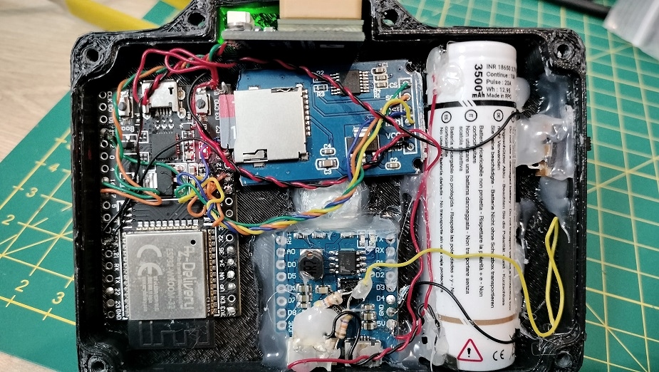
Now solder the wires to the corresponding ESP32 GPIO pins.
It’s starting to look pretty ugly now, isn’t it? 🙂
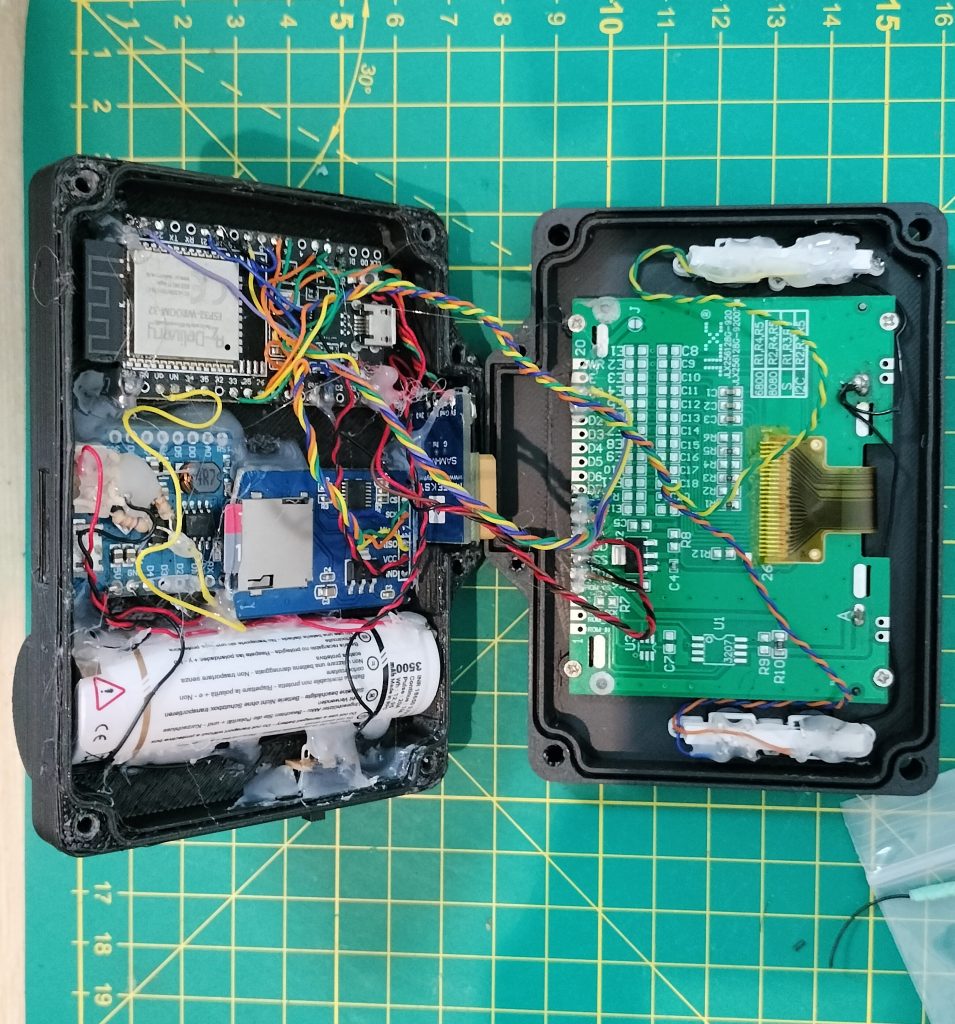
Now connect the display and button wires to their corresponding pins on the ESP32.
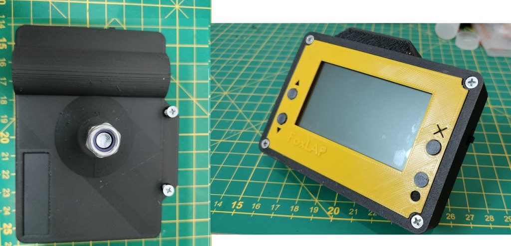
(Only after Point 4 and 5 have been completely done)
But before closing the box, you have to flash the board with the firmware. See Point 5. Firmware installation to do it.
Close the enclosure and secure it with six M3 × 16 mm screws.
Then glue the front panel into place. I printed mine in yellow, but of course, yellow is not mandatory! 🙂
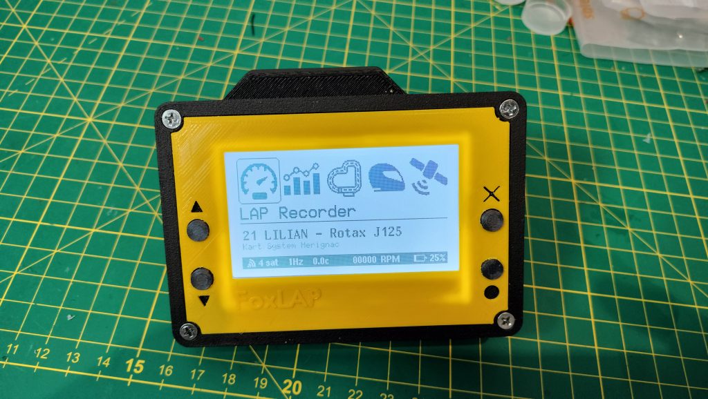
It should be working now… And it definitely looks better once you can’t see what’s inside. 😄
Obviously, the dedicated-board version is much easier to assemble. It also includes a larger display and many more features. If you are interested in the dedicated-board version, you can find more information on this page
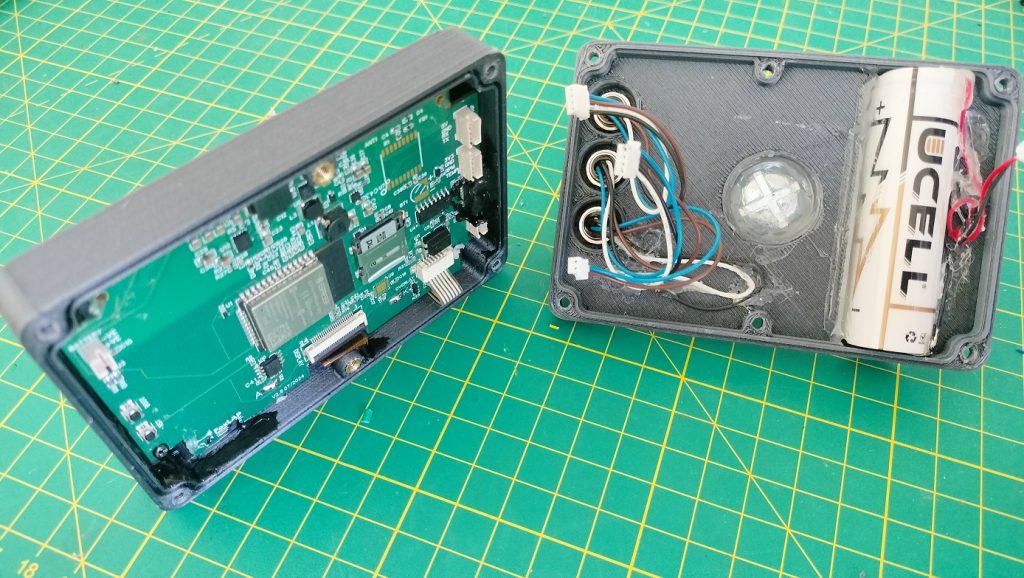
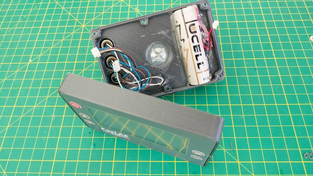
Partitions larger than 32 GB will not be recognized by the device. So if the SD card is not detected, make sure that:
If your SD card has a capacity greater than 32 GB, you will need to create a 16 GB or 32 GB partition. Any remaining space on the card will not be used.
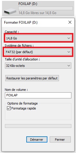
Format the SD card using the FAT32 file system.
Once the formatting is complete, the SD card will be empty and ready to be inserted into the device.
Download this zip file containing the firmware and the tools to flash the board.
Version 2.14 – release date 2026/05/20
What’s new in version 2.1X:
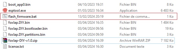
Unzip the contents of the downloaded archive. Connect your ESP32 board to your computer via USB, then run the flash_firmware.bat file.
You will be asked to enter the COM port used to communicate with the board. Enter it like this:
COM6Of course, if your board is using a different COM port, replace COM6 with the correct one. And please don’t contact me just because COM6 is not recognized — your board may simply be using another COM port. 😄
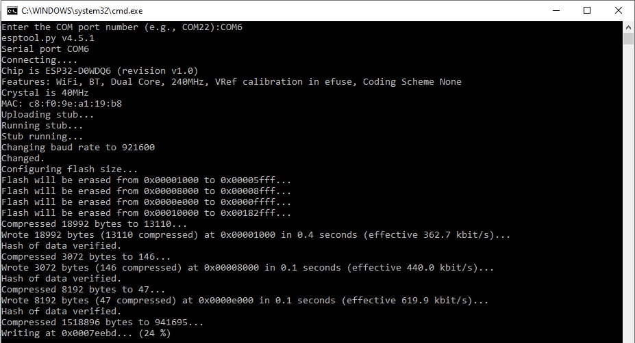
Or you can enter directly the following command
esptool.exe --chip esp32 --port COM6 --baud 921600 --before default_reset --after hard_reset write_flash -z --flash_mode dio --flash_freq 80m --flash_size 4MB 0x1000 foxlap.DIY.bootloader.bin 0x8000 foxlap.DIY.partitions.bin 0xe000 boot_app0.bin 0x10000 foxlap.DIY.bin
Now Hard reboot the board. OK, now the device must be working…
Start your FoxLAP device, then go to:
WiFi transfer → Start WiFi
If you have not yet set a WiFi password, go to:
WiFi transfer → Set WiFi password
Your password must be at least 8 characters long.
Once this is done and the device is running in WiFi mode, you should see “WiFi Data Transfer” on the screen, along with the name of the hotspot created by the device, for example:
FoxLAP_xxxxxx
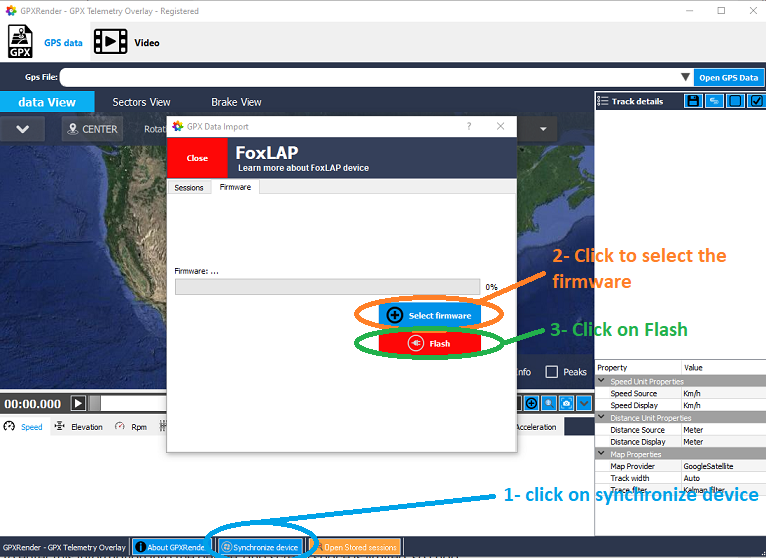
On your computer, connect to this WiFi hotspot. Remember that WiFi passwords are case-sensitive. Then open GPXRender, available on this website, and click “Synchronize device”.
If your computer is correctly connected to the FoxLAP device, a window will appear. Go to the Firmware tab, select the new firmware file, then click Flash. You can now update the firmware over WiFi without having to open or disassemble the device.
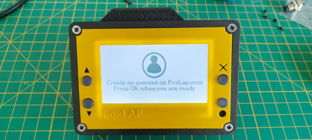
At the first launch, you must get this screen. If it is not already done, create a FoxLAP account here
You will need to enter your name, choose a password, and provide a few other details. Some characters are not allowed, so please pay attention when choosing your login information. You will need to enter the same information directly on the FoxLAP device, and since screen space is limited, I had to restrict the list of supported characters.
Only these characters are allowed at this time: 0-9, a-z, A-Z, ! # $ % & ‘ ( ) * + , – . @ : ; =
What you need to enter during the first startup is shown in this video. The device must be able to connect to the Internet, so you will need to enter your WiFi credentials. You may have trouble with WiFi passwords containing special characters that are not supported by the device. In that case, you can share your phone’s Internet connection by creating a mobile hotspot with a password that only contains characters supported by FoxLAP.
If the connection is unsuccessful, turn off the device and restart it to try again.
Once the connection is successful, the device will automatically retrieve the settings stored in your account, which are available on this page https://foxlap.com/mydevice.php
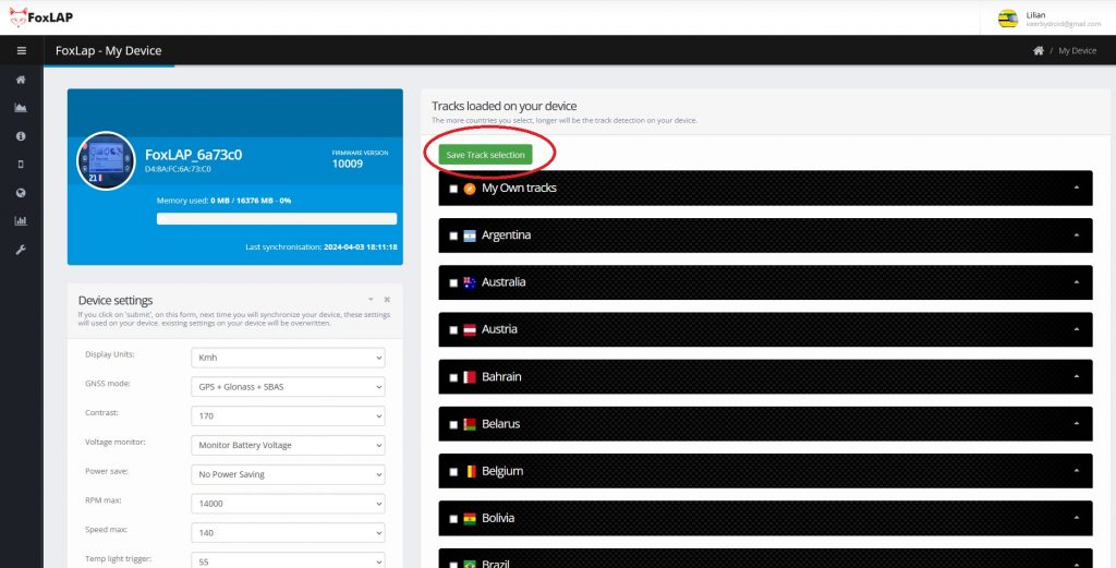
You will be able to change the device settings and also select or unselect the tracks available on your FoxLAP. Do not select all tracks. Only select the tracks from your country or the ones you are likely to use. The more tracks you select, the longer the automatic track detection may take. After changing your track selection, don’t forget to click “Save Track Selection”.
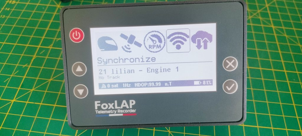
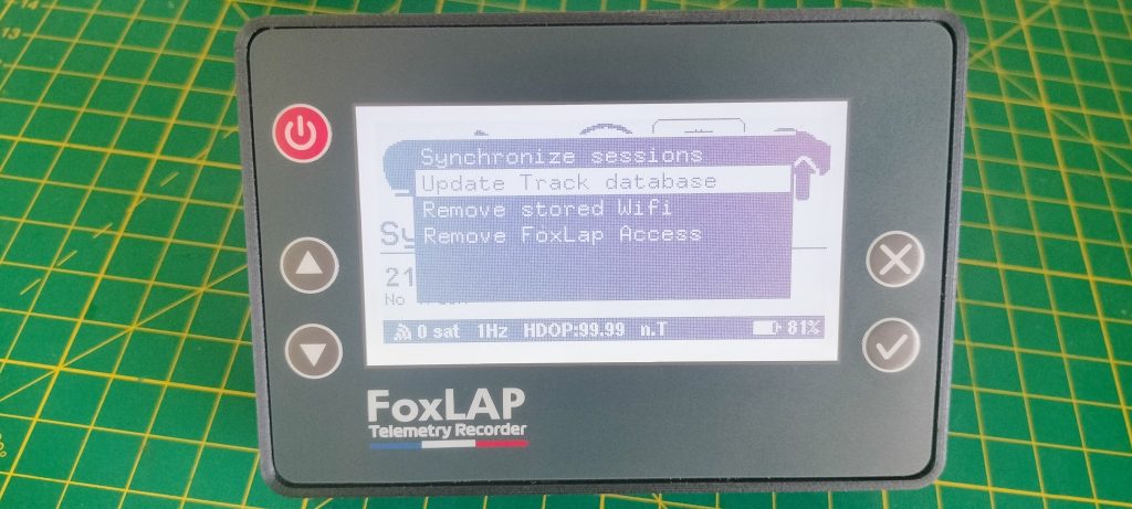
Then, on the device, go to the “Synchronize” menu and select “Update Track Database”.
I recommend creating your own track using the tool provided here: https://foxlap.com/track_creation.php
Once the track has been created, go to https://foxlap.com/mydevice.php, select your newly created track in the “My Own Tracks” category, then click “Save Selection”. Then, on the device, go to the “Synchronize” menu and select “Update Track Database”
I will add more information and tutorials explaining how to use everything. But please keep the following points in mind:
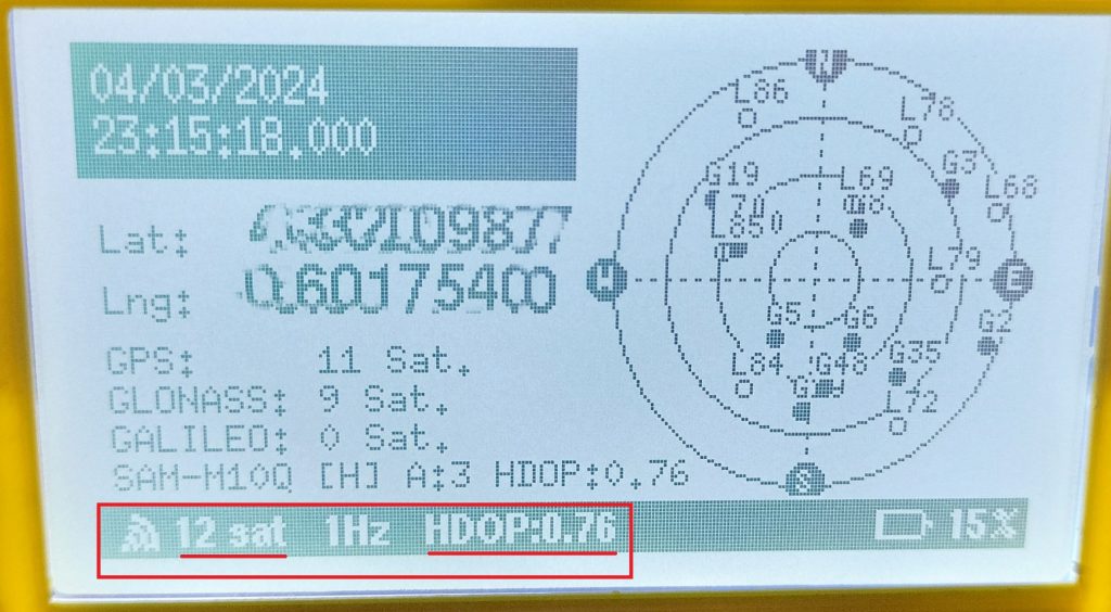
Turn the device on and leave it stationary for a while before driving, to allow the GNSS receiver to obtain a good and stable position fix.
I have one important requirement regarding commercial distribution: you may not sell this DIY version. Commercial use of the DIY version is not permitted.
That’s all for the moment,
Renan BROQUIN

Add a standard WS2812B addressable LED strip to display sector performance and live delta information. Update FoxLAP to the latest firmware before enabling it.
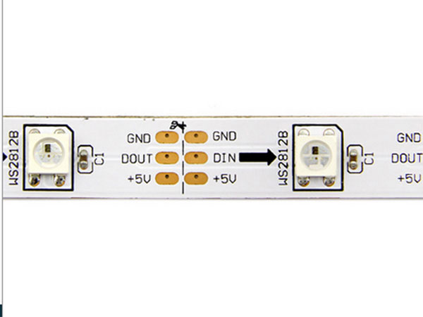
Connect the strip ground to FoxLAP GND, its +5 V input to the 5 V rail and its data input to GPIO12. GPIO12 is safe here because the firmware does not drive it HIGH during boot. Select the number of LEDs in the FoxLAP settings menu.
133 approved comments. Ask a question, share your build or reply to another maker.
A compact GPS lap timer built from readily available parts: ESP32-S3, u-blox GNSS, 256×128 SPI display, microSD storage and a rechargeable 18650 battery.
This FoxLAP DIY tutorial has continued to evolve since its first publication in late 2021. It now includes this compact ESP32-S3 Nano build while retaining the proven FoxLAP operating principles. For reliable GNSS reception, this tutorial uses the MatekSYS SAM-M10Q, which remains fully supported and works perfectly with FoxLAP DIY.
At the end of this tutorial, you will have a fully functional GPS lap timer.

It does, however, come with a few limitations. This DIY version is intentionally focused on the essential GPS lap-timing functions. It is not designed to be fully water-resistant and uses a simple physical power switch instead of an advanced battery-management system.
And yes, the inside is going to look a little rough, with hand-soldered wires and hot glue!
This is intentionally a quick and simple implementation. The first FoxLAP prototype was built in almost exactly the same way so that I could start developing the firmware. I rebuilt one for this tutorial without spending too much time trying to make the internal assembly perfect. I’m sure many of you can build something cleaner — and if you do, please share it!
Despite these limitations, you still get the essential FoxLAP features: lap timing, gap to best lap, speed, sectors, theoretical best lap, live delta and session recording. You can also analyse your recorded GPS data afterwards using GPXRender software or with the online tool
The goal of this tutorial
The aim is to build the simplest possible FoxLAP device using readily available components. This is very close to the hardware i originally used when I started developing FoxLAP, so rebuilding it for this tutorial brings back a few memories
Is it the ultimate hardware design? Definitely not. Could some components be replaced with better or cheaper alternatives? Of course.
Why Blender? Why this display? Why this ESP32 board? There are plenty of choices that could be debated or improved. But this version exists, it works, and it is relatively easy to reproduce.
So, ready to build one?
This is what I used, mainly because I already had most of these items at home. Some of these parts can be replaced with more convenient or cheaper alternatives, depending on what is available in your country.
I have included links to purchase the components, but I have no affiliation with these sellers and I do not earn anything from these links. You are of course free to buy the parts wherever you prefer.
ESP32-S3 Nano option to select: choose “Not welded”. This version is supplied without the pin headers already soldered, making it suitable for the compact FoxLAP DIY assembly.


More & important informations:
1- GNSS module: this tutorial is designed to use the MatekSYS SAM-M10Q mounted inside the enclosure. However, you can probably use any genuine u-blox GNSS module. Please avoid very cheap GNSS replicas. A $5 GNSS module is unlikely to provide the accuracy and reliability you want for lap timing. You can find cheaper genuine u-blox modules such as the M8N, but you will be limited to 10 Hz. That is still perfectly usable — for comparison, the Alfano 6 GNSS also runs at 10 Hz. With some M8N modules, you may not be able to install the GNSS receiver inside the enclosure, so it will have to remain external. In that case, you will need to adapt the 3D enclosure model. I already have a few 3D models designed for this type of configuration.
I had good results with this u-blox M8N receiver:
https://www.aliexpress.com/item/32748573256.html
At the moment, this project is only compatible with u-blox GNSS chips. I may add support for other GNSS modules in the future if they prove to be reliable, accurate and affordable. Some users have also successfully used the QUESCAN M10Q.
Note: on first startup, FoxLAP attempts to communicate with the GNSS receiver at 9600 baud. Depending on the module you use, you may therefore need to configure the GNSS receiver before installing it.
2- Display: this JLX 256×128 COG is sold in separate 5 V and 3.3 V versions. For the ESP32-S3 Nano build, you must select the 3.3 V White SPI version. Connect VDD and LEDA only to the Nano 3V3 pin.
Important — do not use the 5 V display version with this ESP32-S3 Nano wiring. The required model is the 3.3 V SPI display. Never connect its VDD or LEDA pins to the 6.5 V VIN supply.
Important: the display must be both the 3.3 V version and the SPI version.
3- MicroSD card: the ESP32 cannot directly use FAT32 partitions larger than 32 GB, so I recommend using a card of 32 GB or less. If you use a larger card, you will first need to create a 32 GB FAT32 partition on it. For this project, even 16 GB is already more than enough. As with the GNSS module, avoid cheap no-name microSD cards. They can cause all kinds of read/write errors and intermittent problems that are extremely frustrating to diagnose. I have already wasted far too much time with cheap cards before eventually throwing them in the trash! Use a reputable brand and save yourself the headache.
4- 18650 battery: again, don’t be fooled by unrealistic specifications. Avoid no-name batteries advertised as 12,000 mAh or similarly impossible capacities. Use a good-quality 18650 cell from a reputable manufacturer. The battery’s positive and negative terminals must be flat.
With batteries that have a raised button-top terminal, it may be difficult or even impossible to fit the battery into the slot provided in the enclosure.
I’m not a 3D-printing expert, but I got my best results by printing the STL models this way. In the screenshot, I assembled all the STL parts together only to show you how they are positioned. In practice, I printed each STL part separately, not all together as shown in the image.
There is also 2 other parts printed with flexibale filament. You will need two M8 flat-washer parts. They will help you mount the lap timer securely to the steering wheel. This filament gives very good results, but it is quite expensive, and you probably won’t want to buy an entire spool just for two small parts. You can try printing them with regular PLA instead.
Here is the STL files you must print:
The TP4056 charges and protects the cell. The MT3608 raises the changing battery voltage to approximately 6.5 V for the Nano VIN input.
Solder both capacitors directly between the Nano VIN and GND pins, with the leads as short as possible. Use an electrolytic capacitor rated for at least 10 V: positive lead to VIN, negative lead to GND. The 100 nF ceramic capacitor is not polarized. A 10 µF capacitor can be used for initial testing, but 220–470 µF provides a much better reserve against Wi-Fi and microSD current peaks.
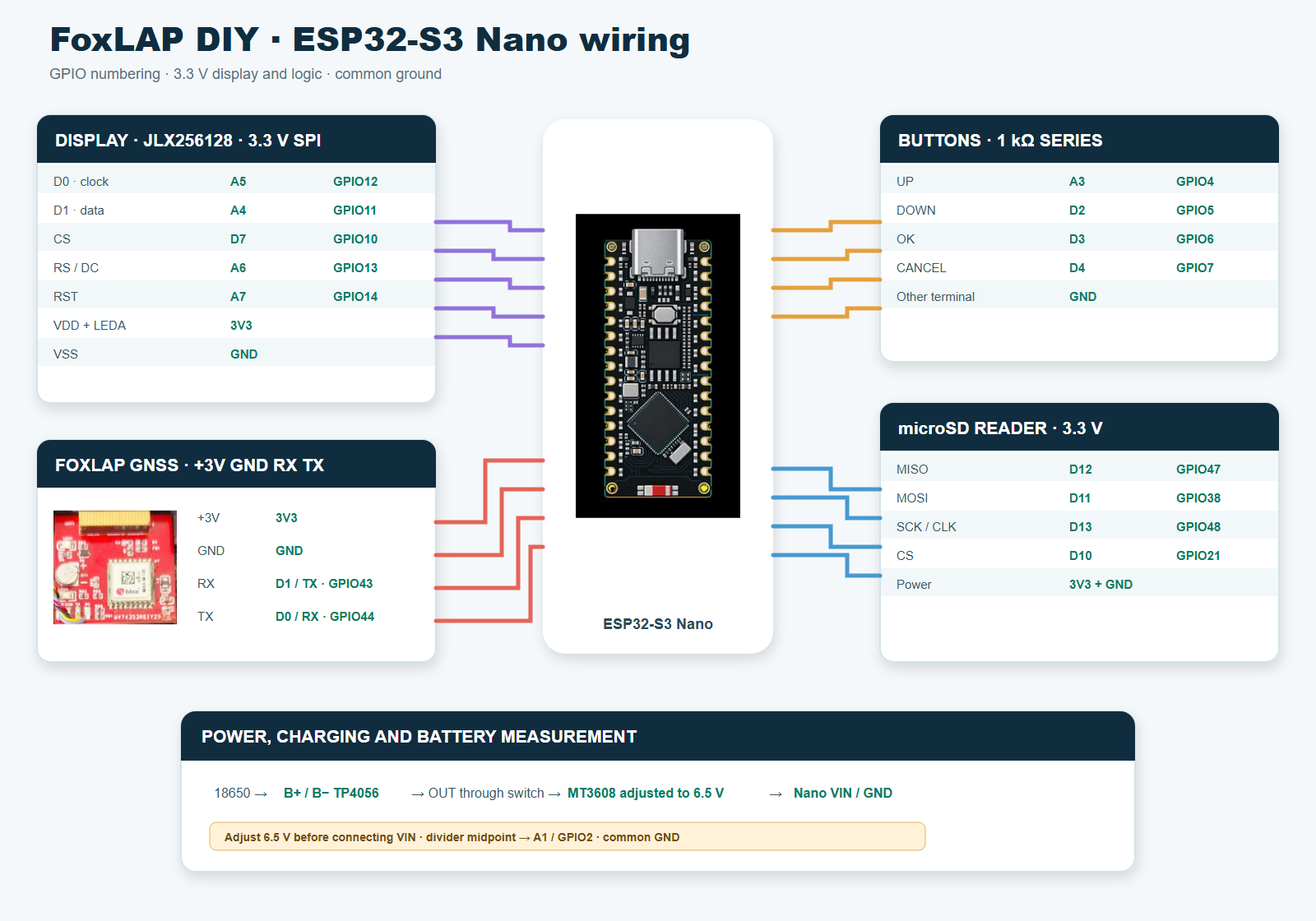
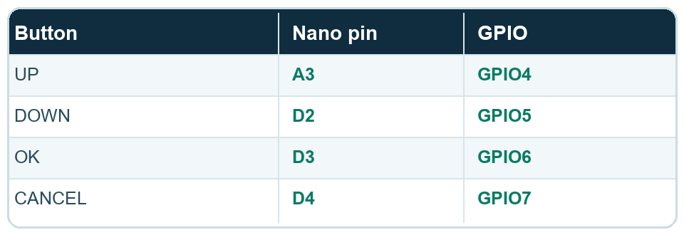
The labels below are the names printed on the Nano board. The GPIO column is the number used by the firmware when “ESP32S3 Dev Module” is selected.
| Display marking | Function | Nano pin | GPIO | Notes |
|---|---|---|---|---|
| D0 | SPI clock | A5 | GPIO12 | Hardware SPI CLK |
| D1 | SPI data | A4 | GPIO11 | Hardware SPI MOSI |
| CS | Chip select | D7 | GPIO10 | Active LOW |
| RS | Data / command | A6 | GPIO13 | Called DC in the firmware |
| RST | Display reset | A7 | GPIO14 | Explicitly driven by U8g2 |
| VDD | Display supply | 3V3 | — | 3.3 V display only |
| VSS | Ground | GND | — | Common ground |
| LEDA | Backlight anode | 3V3 | — | For the 3.3 V white model |
| microSD | Nano pin | GPIO | Notes |
|---|---|---|---|
| MISO | D12 | GPIO47 | SD data to ESP32 |
| MOSI | D11 | GPIO38 | ESP32 data to SD |
| SCK / CLK | D13 | GPIO48 | SD clock |
| CS | D10 | GPIO21 | SD chip select |
| 3V3 | 3V3 | — | Use a 3.3 V-compatible module |
| GND | GND | — | Common ground |
| GNSS | Nano pin | GPIO | Notes |
|---|---|---|---|
| GNSS TX | D0 / RX | GPIO44 | Cross TX from GNSS to RX on Nano |
| GNSS RX | D1 / TX | GPIO43 | Cross RX from GNSS to TX on Nano |
| +3V / supply | 3V3 | — | Power the MatekSYS SAM-M10Q from 3.3 V |
| GND | GND | — | Common ground |
| WS2812B LED bar | Nano pin | GPIO | Notes |
|---|---|---|---|
| DIN / Data in | D6 | GPIO9 | S3 firmware LED control signal |
| VDD / + | 3V3 | — | Only for a certified 3.3 V-compatible WS2812B-V6 strip |
| GND | GND | — | Common ground with the Nano |
| Function | Nano pin | GPIO | Connection |
|---|---|---|---|
| Main supply | VIN | — | Approximately 6.5 V regulated output from MT3608 |
| Common return | GND | — | TP4056, boost, Nano and peripherals |
| Bulk capacitor | VIN ↔ GND | — | 220–470 µF / 10 V minimum; + to VIN, − to GND |
| High-frequency bypass | VIN ↔ GND | — | 100 nF ceramic, placed directly beside the Nano pins |
| Battery measurement | A1 | GPIO2 | Midpoint of two 10 kΩ resistors across the battery |
From this point on, you should have the 3D-printed enclosure and all the electronic components in front of you. The complete ESP32-S3 Nano wiring map is shown immediately above. Use that map throughout the assembly: the former ESP32 DevKit and Wemos battery-shield diagrams do not apply to this version.
3.1 Buttons assembly
Insert the four buttons into the button holder you printed earlier.
Make sure the buttons slide freely without binding. Enlarge the holes slightly if necessary, as 3D printing can sometimes leave a small amount of excess material around the edges.
Then attach the button-holder parts using M1.2 × 5 mm screws. Repeat the same process for both the left and right button assemblies.
Connect all the button ground pins together, then connect them to the display’s K ground pin. Use a different wire color for each button. This will make it much easier to identify the correct wire when you solder them to their corresponding ESP32-S3 Nano pins later. It’s time to add the 4 debounce resistors on the buttons.
IMPORTANT: you may not have to add the debounce resistors (even if it’s not recommanded). But you must add them if you are willing to use the device in engine environnement
Apply hot glue to all solder joints. Remember: vibration is our enemy. Leave enough length on the wires, as you will need to solder them later to the ESP32-S3 Nano located in the other half of the enclosure.
3.2 Display assembly
Install the display and secure it with the screws. You can add a small amount of hot glue to help position the display correctly and make sure it does not move.
Use the ESP32-S3 Nano display table above for every electrical connection. Prepare and solder the wires to the display, but do not solder them to the ESP32 yet. Again, leave enough length on the wires, as you will need to connect them later to the ESP32-S3 Nano located in the other half of the enclosure.
3.3 Bottom part assembly
Place the power on/off switch and secure it with hot glue.
Insert the M8 × 30 mm screw, apply a small amount of regular glue to the top of the screw, then tighten it into place.
Fill the remaining space around the M8 screw head with hot glue to secure it firmly in place.
3.4 Battery, charger and 6.5 V converter
Now take your 18650 battery and use a spot welder to attach nickel strips to both terminals.
Place the battery inside the enclosure and apply hot glue around it to hold it securely in place.
Connect the cell to the protected TP4056 charger: battery positive to B+ and battery negative to B−. Place the power switch between the TP4056 output and the MT3608 input so the complete FoxLAP circuit can be disconnected while the battery remains connected to the charger.
Connect the midpoint of the two 10 kΩ battery-measurement resistors to Nano A1 / GPIO2, as shown in the S3 wiring map. Keep the MT3608 wires short and route its inductor and power wiring away from the GNSS antenna and SPI cables.
3.5 GNSS assembly
Install the MatekSYS SAM-M10Q and power it from the Nano 3V3 pin. Connect GNSS GND to the common ground, GNSS TX to Nano D0 / RX (GPIO44), and GNSS RX to Nano D1 / TX (GPIO43). Position the antenna away from the ESP32 antenna and the MT3608. Do not power the GNSS module from VIN or from the 6.5 V rail.
Important antenna position: the GNSS antenna must always face the sky. Nothing may cover or pass over the antenna: no cable, electronic board, display or other component. Only the plastic of the enclosure should be above it.
3.6 SDCARD assembly
Install the microSD reader and connect MISO, MOSI, SCK and CS to the Nano pins shown in the S3 wiring map. Power the reader from 3.3 V and connect it to the common ground. Keep these SPI wires short and away from the MT3608 inductor.
3.7 Wire to the ESP32-S3 Nano
Solder every wire to its corresponding ESP32-S3 Nano pin using the wiring map above. Now connect the display and button wires to their corresponding pins on the Nano. Insulate exposed conductors and apply hot glue to the solder joints and modules once every connection has been tested.
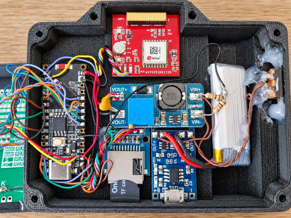
The prototype shown in this photograph uses a different battery. For this build, it is better to use a standard 18650 cell as specified throughout this tutorial.
The photograph above shows the internal arrangement with the ESP32-S3 Nano, GNSS receiver, microSD reader, protected TP4056 charging module, MT3608 boost converter and battery. Component positions may be adjusted, but keep the GNSS antenna clear and make sure no wire can pull free under vibration.
Keep the power switch OFF while checking the wiring. The final connection, firmware and enclosure-closing steps continue below.
Now connect the display and button wires to their corresponding pins on the ESP32-S3 Nano.
(Only after Point 4 and 5 have been completely done)
But before closing the box, you have to flash the board with the firmware. See Point 5. Firmware installation to do it.
Close the enclosure and secure it with six M3 × 16 mm screws.
Then glue the front panel into place. I printed mine in yellow, but of course, yellow is not mandatory! 🙂
It should be working now… And it definitely looks better once you can’t see what’s inside. 😄
Obviously, the dedicated-board version is much easier to assemble. It also includes a larger display and many more features. If you are interested in the dedicated-board version, you can find more information on this page
Partitions larger than 32 GB will not be recognized by the device. So if the SD card is not detected, make sure that:
If your SD card has a capacity greater than 32 GB, you will need to create a 16 GB or 32 GB partition. Any remaining space on the card will not be used.
Format the SD card using the FAT32 file system.
Once the formatting is complete, the SD card will be empty and ready to be inserted into the device.
Add an optional WS2812B-V6 addressable LED strip certified for 3.3 V operation to display sector performance and live delta information. Update FoxLAP to the latest firmware before enabling it.
Connect the certified WS2812B-V6 bar VDD directly to the Nano 3V3 pin and join its GND to the FoxLAP common ground. This direct 3.3 V connection is valid only for LEDs explicitly specified as WS2812B-V6, 3.3 V compatible; do not substitute a generic or older 5 V WS2812B strip. Never connect the LED bar to the 6.5 V VIN rail. Select the number of LEDs in the FoxLAP settings menu.
Download this zip file containing the firmware and the tools to flash the board.
Version 2.18 – ESP32-S3 Nano
What’s new in version 2.1X:
Unzip the contents of the downloaded archive. Connect your ESP32-S3 Nano board to your computer via USB, then run the flash_firmware.bat file.
You will be asked to enter the COM port used to communicate with the board. Enter it like this:
COM6Of course, if your board is using a different COM port, replace COM6 with the correct one. And please don’t contact me just because COM6 is not recognized — your board may simply be using another COM port. 😄
Or you can enter directly the following command
esptool.exe --chip esp32s3 --port COM6 --baud 921600 --before default_reset --after hard_reset write_flash -z --flash_mode dio --flash_freq 80m --flash_size 8MB 0x0 foxlap.DIY.bootloader.bin 0x8000 foxlap.DIY.partitions.bin 0xe000 boot_app0.bin 0x10000 foxlap.DIY.bin
Now Hard reboot the board. OK, now the device must be working…
Start your FoxLAP device, then go to:
WiFi transfer → Start WiFi
If you have not yet set a WiFi password, go to:
WiFi transfer → Set WiFi password
Your password must be at least 8 characters long.
Once this is done and the device is running in WiFi mode, you should see “WiFi Data Transfer” on the screen, along with the name of the hotspot created by the device, for example:
FoxLAP_xxxxxx
On your computer, connect to this WiFi hotspot. Remember that WiFi passwords are case-sensitive. Then open GPXRender, available on this website, and click “Synchronize device”.
If your computer is correctly connected to the FoxLAP device, a window will appear. Go to the Firmware tab, select the new firmware file, then click Flash. You can now update the firmware over WiFi without having to open or disassemble the device.
At the first launch, you must get this screen. If it is not already done, create a FoxLAP account here
You will need to enter your name, choose a password, and provide a few other details. Some characters are not allowed, so please pay attention when choosing your login information. You will need to enter the same information directly on the FoxLAP device, and since screen space is limited, I had to restrict the list of supported characters.
Only these characters are allowed at this time: 0-9, a-z, A-Z, ! # $ % & ‘ ( ) * + , – . @ : ; =
What you need to enter during the first startup is shown in this video. The device must be able to connect to the Internet, so you will need to enter your WiFi credentials. You may have trouble with WiFi passwords containing special characters that are not supported by the device. In that case, you can share your phone’s Internet connection by creating a mobile hotspot with a password that only contains characters supported by FoxLAP.
If the connection is unsuccessful, turn off the device and restart it to try again.
Once the connection is successful, the device will automatically retrieve the settings stored in your account, which are available on this page https://foxlap.com/mydevice.php
You will be able to change the device settings and also select or unselect the tracks available on your FoxLAP. Do not select all tracks. Only select the tracks from your country or the ones you are likely to use. The more tracks you select, the longer the automatic track detection may take. After changing your track selection, don’t forget to click “Save Track Selection”.
Then, on the device, go to the “Synchronize” menu and select “Update Track Database”.
I recommend creating your own track using the tool provided here: https://foxlap.com/track_creation.php
Once the track has been created, go to https://foxlap.com/mydevice.php, select your newly created track in the “My Own Tracks” category, then click “Save Selection”. Then, on the device, go to the “Synchronize” menu and select “Update Track Database”
I will add more information and tutorials explaining how to use everything. But please keep the following points in mind:
Turn the device on and leave it stationary for a while before driving, to allow the GNSS receiver to obtain a good and stable position fix.
I have one important requirement regarding commercial distribution: you may not sell this DIY version. Commercial use of the DIY version is not permitted.
That’s all for the moment,
Renan BROQUIN
133 approved comments. Ask a question, share your build or reply to another maker.
The DIY version looks great .
I started building something a year ago to check what my motor is doing but life keeps getting in the way. When time permits I am still modifying and improving.
So far I have RPM with LED indicator, temp and GPS data.
Watching with interest as your project evolves.
Gracias por compartir el gran trabajo que has hecho.
Si que es verdad que hay algun bug pero el trabajo es excelente sigo esperando nuevas versiones de firmware !
Gracias y genial trabajo.
Thankyou so much 🙂
Mejoraria el sistemas de dashboard haciendo posible subir las sesiones desde el pc ( que esta la opcion pero no se puede ejecutar) y no via internet desde el laptimer ( es mucho mas lento y poco fiable).
Tambien daria la opcion de subir archivos al dashboard con el formato de Alfano para poder comparar vueltas con los demas pilotos, o a traves de GPXrender algo mas intuitivo que te permita guardar la vuelta rapida como en web para poder comparar mejor.
Insisto todo esto son criticas constructivas, el aparato es lo mejor que puede haber a nivel casero, y seguire probandolo e intentando ayudarte.
un saludo! nos vemos en instagram @pitbikezaragoza
https://www.amazon.com/gp/product/B07JH48HBL
I got one fault, when I tried to record an own track. The device always shuts down and reboots again.
Can you tell me on which pin no the RMP signal can be attached? Or is it possible to get the scetch of the programm to customize it more and more to my preferences?
Thank you so much!
Best regards
Achim
One more here. I first tested the foxlap on known track (with a little change) and worked great.
I tried to show my friend close to my house, but it kept restarting as soon as we started moving.
If we click “create new track” and don´t move, the device was on.
As soon as we moved one meter, it restarted.
As many had said before great job, and I look forward to test it on track.
It looks like I need the 38 pin esp32 borad since you use the GPIO0 pin for display RST. Would you consider change that pin assignment if possible to make it 30 pin board compatible for the simpler DIY version.
Regards Johan
correct, maybe i will do it if i have time to focus again on the DIY version. i made this DIY version in January 2022 to start the development and see if i can get interesting results (the extra pins are interesting to add sensors). I dropped the development board for a dedicated board in may 2022.
Would you consider releasing the DIY version as opensource. You could put whatever licensing limitations on it as you want to keep people from doing stuff you dont want with your work. Then we tinkerers can do these small tweaks and perhaps even contribute to your product.
For my part I just want the accurate gps tracking features. Will run dual devices for engine monitoring until I can get hold of a “fancy” one 🙂
Regards
Johan
Thanks for all the great work and for sharing! About the 18650, can we make the slot provided in the box slightly longer so that we have the option to use 18650 with protection? Or is there protection already built in to the circuit?
Is there circuit protection for the 18650 battery? Reason I ask is I was thinking of going with a protected 18650 but those all have the protruding top; not flat top. Is it possible to amend the 3D drawing to allow for some extra millimeters to accommodate a sightly longer battery?
Thanks,
For the display, I don’t see the model you mention on the N.American version of AE. I only see this – https://www.aliexpress.com/item/32818052799.html?spm=a2g0o.productlist.main.1.5399581bWezmxC&algo_pvid=ab72c4be-7784-451d-b43c-45a3a3bd73ad&algo_exp_id=ab72c4be-7784-451d-b43c-45a3a3bd73ad-0&pdp_npi=4%40dis%21CAD%2118.43%2118.43%21%21%2113.12%2113.12%21%402101e9a217186835696836000e4562%2167306057772%21sea%21CA%212851139477%21&curPageLogUid=DzOdIqsqyMI0&utparam-url=scene%3Asearch%7Cquery_from%3A
The dimensions are slightly different to the one you used. Will this cause an issue with the 3D-printing?
The dimensions for my version:
Outline Dimensions: 79.4*62.8*6.4mm
Active Area: 71.74*38.46mm
The dimensions for your version:
Outline dimensions: 72.1*56.4*6.1mm
Active area: 66*37MM
I am going to use a 3D printing service as I don’t have a 3D printer. In the configuration page, I am offered options such as Supports (Enabled or disabled), Wall count (Default 2), Top Layers (Default 2), Bottom Layers (Default 2), Ironing (Enabled/Disabled). Do you know what choices I should make for these options?
Thanks,
Congratulations excelent project, it is the best project in its category that I have ever seen.
I maked a working prototype, but FOXLAP only shows a maximum of 10hz (I’m using the Mateksys SAM-M10Q GNSS module).
HDOP is always close to 0.7.
The SAM-M10Q datasheet states up to 20Hz for GPS+Galileo or 18Hz for GPS only.
Could you tell me what the problem is?
It seems to me that in firmware 1.2 I lost the Glonass signal, I already did the configuration and it didn’t solve the problem.
How export GPX file from the FOXLAP website to analyze the Hz?
Thank you
Personnellement, j’ai pas la patience de collecter tous les objets sur Aliexpress.
J’ai ete au plus rapide….
Mini ordinateur windows 11 avec processeur N100 et un ecran tactile de 5 pouces etanche
Total 120 Euros sur Ali livré en 2 jours…;
Est t’il possible d’ajouter une lecture a partir d’un port ou usb pour le gps et aux capteurs depuis le logiciel sans avoir a monter la totalité de l’artefact….,????
Je m’explique, l’ordinateur peut afficher la carte en direct grace a googgoole, et la partie chronometre avec la trajectoire son enregistres en dur sur le pc embarqué (ok ok, 1kg en total en plus) en lecture instannée… de ce fait on peut comparer en réel (afficheur tete haute dans le casque….) On tue le game la mais…..je peux envoyer des photos de mon montage….
Connecting a button to 3.3V with a resistor, typically referred to as a pull-up resistor, is a common practice to debounce the Button Presses. It is not mandatory to debounce the buttons but it is recommanded
I ordered 3d prints for all the parts and I picked them up today! Exciting times! I am trying to attach the button holders. Should there be a gap between the bottom of the button holders and the buttons?
Having the lambda and rpm values would be so great. Will you integrate these features in the DIY version as well? This would be so helpful!
Thank you!
Thank you!
https://nabucasa.github.io/esp-web-flasher/
Maybe it will help someone how does have the same problem.
Very very nice project!!
Thanks a lot
1- You are located inside a building or somewhere you don’t have a direct access to the sky
2- Your GNSS receiver is a poor replica and is not a m8n but a m6n or something else but advertised as a m8n
3- Or it can be an issue with your antenna
The firmware configure the GNSS receiver automatically if an m8n, m10n, m10Q is discovered. So maybe check that you ship is a real m8n
Its posible to add magnetic sensor for indoor use? (Only laptime)
You are awesome 👍
I built the DIY version and I bought the sensor box. I assembled everything and it works nice, except one thing.
If sensor cables between ESP32 board and M8 connector are touching each other, then I have RPM signal around 13800-13900, so these 2 cables are interfering.
Can you suggest what to do with this problem?
Thanks in Advance!
This is an awesome project
I’m testing the diy version and found a few bugs:
1. If guest driver is deleted from the list of drivers (which can be done from the UI), the device wouldn’t load again. It just shows blank screen after loading.
2. Disabling voltage monitor in the settings doesn’t seem to do anything. Battery status is still showing in the bar.
I also experienced the same symptom after deleting GUEST driver, so +1 to this bug.
Actually I just realized, this is the reason I have blank screen after loading. I thought I have other problem.
Thanks for sharing this information.
i can’t reproduce this issue.
I have been working on the DIY timer and followed the directions. I have flashed the hardware and rebooted but other than the screen lighting up I am not getting anything on the display.
I am a bit of a novice but I have checked the wiring and cannot find anything obviously wrong.
Are you able to suggest any possible advice?
Thank you.
It has a much better price compared to the others.
thanks.
It takes a lot of time to test a GNSS, and most cheap GNSS do not give good results. I stick with what I know and what I know gives good results
during a test a bad lap has been recorded and now is fixed as best lp of that circuit, that is wrong. I have already deleted this session on Folap and also on online account but wrong best lap still remain linked to the circuit. How can i do to remove it?
Thanks a lot in advance
Ciao
Andrea
Solution 2: (The free way) remove the SDcard from the device, insert it into a computer. Open the file “drivers.xml” located at the root. you will see in this file the UID of the driver. This UID is also the name of a directory located at the root of the sdcard. open this directory, and open the file “record.xml”, you will be able to edit the content and change the best lap time with whatever you want. ATTENTION to formatting.
I’ve tested it on several WIFI networks, all with high speeds, but I always notice this slowness.
Can anyone tell me if they’ve experienced this before or if there’s any way to fix it?
Reduce file size: Lower your GNSS update rate (e.g. from 25 Hz down to 10 Hz) in Settings > GNSS Mode. Fewer data points mean smaller session files and faster uploads.
Optimize your Wi-Fi link: Make sure you’re on a 2.4 GHz network (the device doesn’t support 5 GHz).
Position the device as close as possible to the access point, with minimal obstructions.
Check for firmware updates
We regularly improve transfer performance. download and install the latest build.
Unfortunately I have a problem: my sd is not detected.
I tried a 4gb sd and a 16gb. The message “waiting sd” remains and then it starts. What could it depend on?
The only thing it needs is a live time delta (to show your time live in comparison to your fastest time during each lap, so you can see exactly where your are faster or slower while driving).
I think this is a really popular feature and I wanted to ask if there is a way I get my foxlap timer to show a live time delta?
I look foward to hearing from you! 🙂
– Harry
Would it be possible that you make one additional screen, so that only the value of live delta is visible over the whole screen (big numbers)?
And perhaps switch the color of numbers and background when the value is positive to see that we are slower without reading the numbers.
And would it be possible to get this live delta for each segment compared with the fastest segment?
Thank you so much!
Best regards
I have another idea for a new feature:
It would be nice to connect a small LED strip that lights up green when the live time delta is faster. This would work similar to how the Mychron and Alfano systems show a green light when you improve your lap time. The green light is just a quick way to see that you are going faster, without needing to look at the screen.
This could be done by soldering a small LED strip onto the board. Here is an example LED strip: https://phaserfpv.com.au/products/tbs-tiny-leds-femto-8-led-4pcs?variant=31904785825869&country=AU¤cy=AUD&utm_medium=product_sync&utm_source=google&utm_content=sag_organic&utm_campaign=sag_organic&gad_source=1&gad_campaignid=21891404095&gbraid=0AAAAAC7E5-QeRY2rC9ne-dw9-BvtuQb8V&gclid=Cj0KCQjw5JXFBhCrARIsAL1ckPtGefUGCSYGIaxiAsJ6LTvJ_8IwaN8y87EiY2-WSJIL5kDzsgyix3AaAtoNEALw_wcB.
These strips are often used on FPV drones and usually have three pads: ground, power, and an LED pad for controlling the color and effects.
Do you think this could be possible to add? I think it would be a really cool feature!
The leds can also be used as a Tacho
similar to https://github.com/MickTheMechanic/Shiftlight
– RPM level as a bar graph
– Live delta indicator
– Sector times (2 LEDs per sector, green or red — no need to explain what that means)
– … if you have any ideas … please tell me
These NeoPixel LED strips are affordable (as shown in the picture) and work as a quick-and-dirty solution, but under direct sunlight they’re almost invisible. That’s why they won’t fit our needs. I’ll have to use brighter LEDs with directional lenses instead. I will post on the progrees of this addon. i’ve already made a prototype.
Thank you
Thank you.
Brownout Detection is a safety feature on the ESP32 that monitors the power supply voltage. If the voltage drops below a safe threshold, the ESP32 automatically resets to prevent unpredictable behavior, data corruption, or potential damage to the chip.
In some cases, you might choose to disable brownout detection—especially if the ESP32 is powered by an unstable source, which can cause false brownout triggers and unnecessary resets.
By default, brownout detection is enabled.
PCNT (Pulse Counter) is a hardware peripheral on the ESP32 used to count digital pulses (signal transitions) on specific GPIO pins.
It is disabled by default and typically does not need to be activated unless specifically required for a particular use case.
i had 2 or 3 users from your country with the same issue (i think it is related to DNS). i’m working on it.
Setting => Synchronization mode => 2.Secured
(The TLS stack consumes a significant amount of memory and leaves the heap fragmented. Use this mode only if the device cannot be synchronized in the default mode. In secure mode, the device will restart after each synchronization process because the heap remains too fragmented, and restarting is the only way to restore a clean heap)
Thank you, love this DIY, very well done.
Leave RST unconnected: the display may rely only on its internal power-on reset; sometimes it works, sometimes it doesn’t (risk of random behavior).
Best practice: keep RST on the given GPIO. No there is no way the change the GPIO
Thank you so much.
I’m in Lithuania, but while testing at home, i have a problem with satellites doesn’t want to connect, or with only 1-2. HDOP very high.
Already tested lap recorder, works fine, love it.
Thank you.
Does the dedicated version have an integrated accelerometer? Would it be possible to connect this module to the DIY version as well?
Thanks
You’re the best…..
Firstly, thank you for sharing this awesome project. It is truly interesting and helpful for those interested in using it while driving rental karts. Also, the cost is significantly lower than buying a MyChron, for instance.
I’ve been using it since last month and I noticed that there is an option to connect a GoPro to it. I got the version.txt file from my GoPro and copied it to the GoPro folder inside the microSD card. When I try to connect to my GoPro, Foxlap shows the following message: “waiting smart remote…”. I tried connecting my GoPro through the remote connection, but with no success.
Can indicate what am I doing wrong? and what do I get by connecting the foxlap to my gopro?
With the help of the videos with lap overlays make it so interesting to view at later times.
Noticed LED controller in the last firmware, does this mean it’s past prototype and is there a GPIO pin assigned?
Could you also grace us with an RPM reading? That would be wonderful.
Was this track selected on the lap timer?
Were you driving in the correct direction on the created track? If you drive in the opposite direction, the lines won’t be detected.
Do you have a session recorded on the lap timer? If so, please share it with me.
UPDATE: I flashed firmware v2.03 and everything works fine, so the problem in the firmware 2.04. I created test track near my home and ran 3 laps, firmware 2.04 displays position, speed, but do not record session, do not count time after first crossing the start line, firmware 2.03 start recording session and counting time after first start line crossing and stop recording after I stopped my car. all the settings was the same.
And another one bug: I created only one track (test track), but after 3 synchronizations device displays 3 duplicates in the tracks menu. The same behavior with 2.03 firmware
bug identified for duplicated entries in track list after update (will be fixed in next coming versions)
To fix this I have now replaced the V1.1.0 Battery Shield with a V1.2.0 Battery Shield.
With V1.2.0 Battery Shield and the Foxlap unit switched off battery discharge from 100% charge to 75% charge takes about 30 days.
When foxlap unit is switched on and being used on the track both of the shields are about the same, discharge is 100% to 40% for about 7 hours continual use.