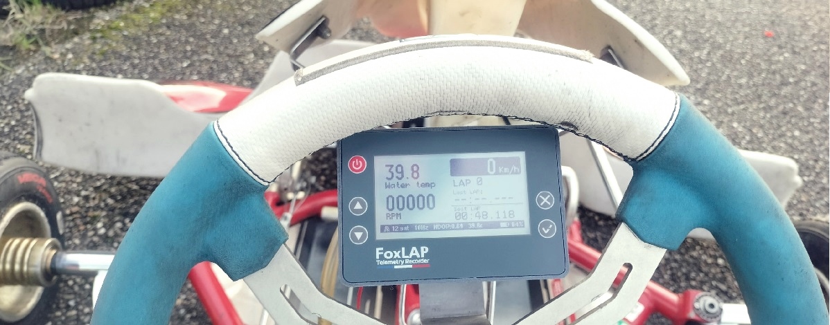
The purpose of this post is to present the Pro version of the FoxLAP device, built on its dedicated board. This board has been developed and tested over the past two years, and has already been used in competition here in France by my son and other drivers. With two years of technical feedback, we can confirm that this PCB is both reliable and efficient.
It features a larger 3.2-inch display, and the overlay with integrated buttons not only protects the screen but also gives the device a more refined look.
Experience what it’s like to drive with a FoxLAP Lap Timer.
1. Dedicated Board version
In this tutorial we will build a FoxLAP device based on the dedicated board and working with both the external sensor pack and the sensors given with the dedicated board
1.1 – Print the model
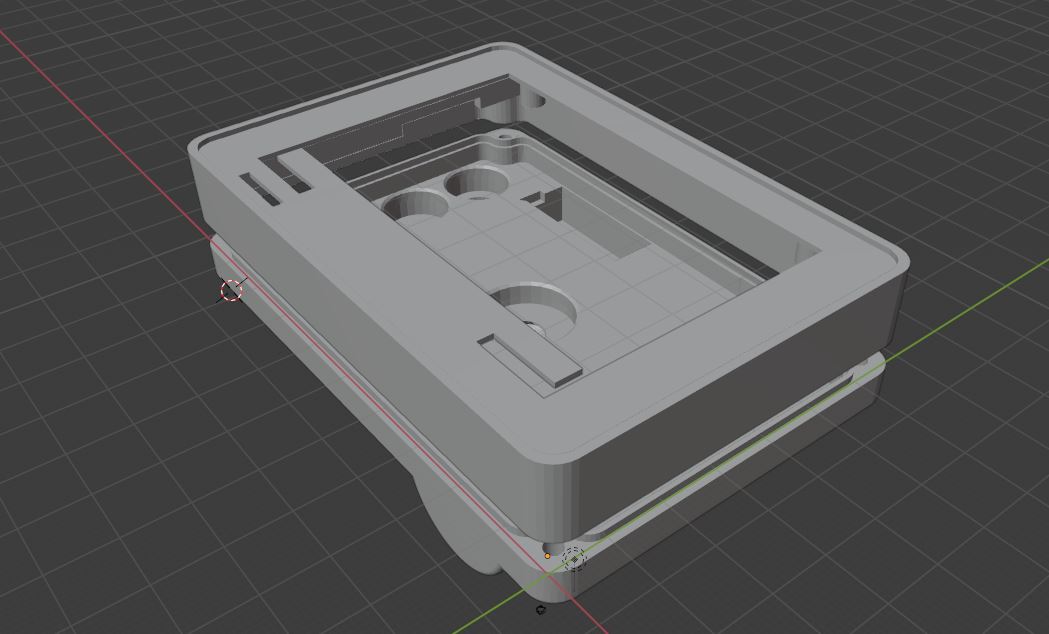
- STL files were created using Blender.
- 3D Printer: Bambulab X1 Carbon.
- Slicer: Bambu Studio
- 3D filament: 1.75mm Bambu PETG-CF Black filament
- Print settings: 0.4mm nozzle, Standard quality (0.16mm), 40% infill, Support (zig zag support)
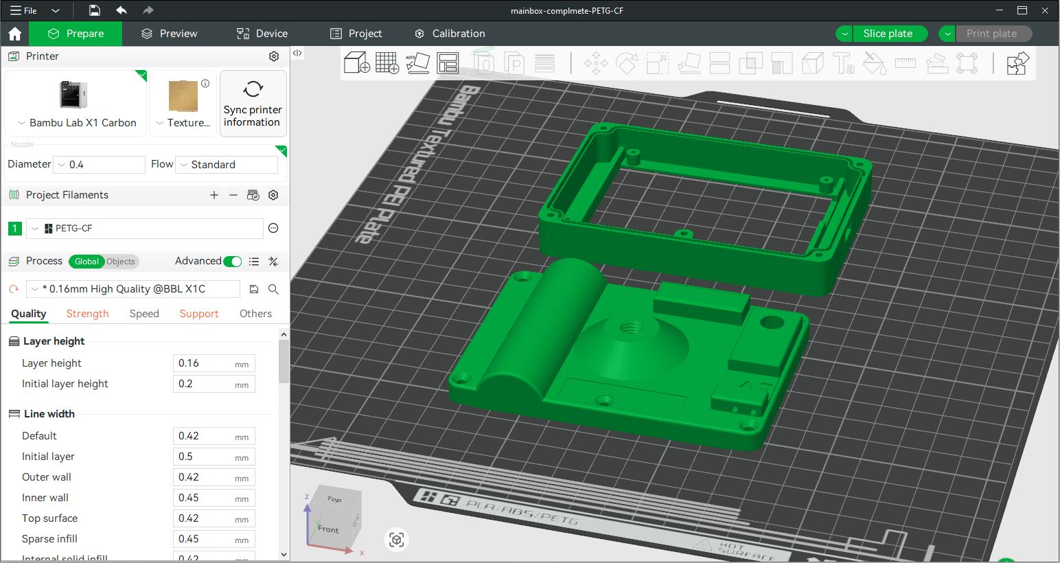
The zip contains both top an bottom part
1.2 – Get required parts
The board is coming with the display. The firmware is also alreday on it – no need to flash the board.
FoxLAP – Dedicated board pack
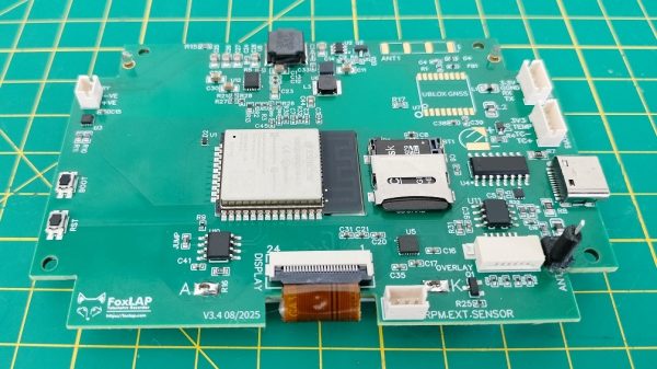
FoxLAP – Dedicated board pack include: PCB including display & RPM Sensor, Overlay with switch buttons, RPM cable, Water temperature probe, M8 Cable with temperature connectors, RPM Sensor included on the main board, M8 connector, 4GB SDCARD, JST 4 pins (for the external GNSS), JST 2pins (for the battery), Screws, More info
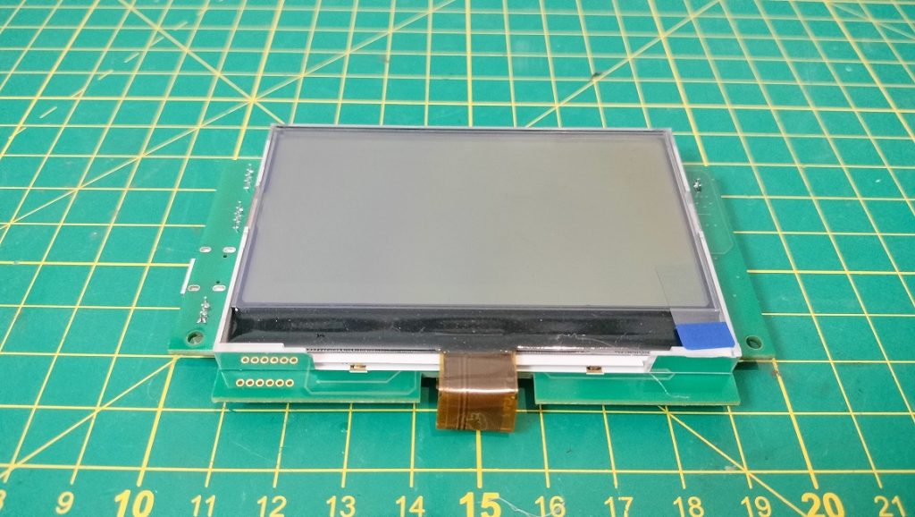
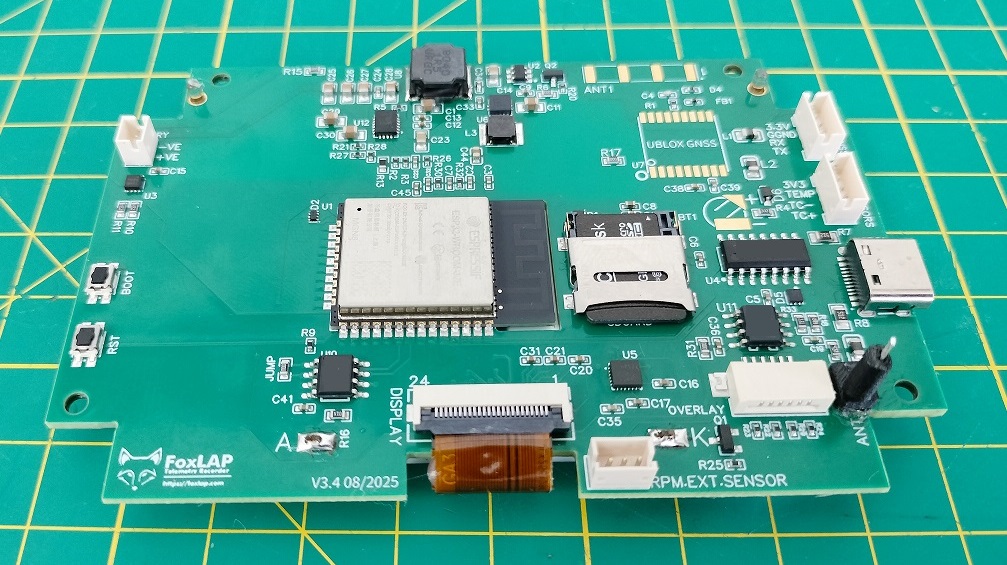
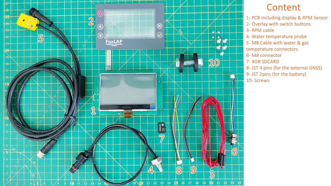
I made a package including what you will need. The FoxLAP dedicated pack includes:
- 1 FoxLAP dedicated PCB board (display included & RPM Sensor).
- 1 adhesive overlay layer with push buttons
- 1 M8 connector (will be mounted at the bottom of the FoxLAP device) with JST connector for external sensors
- JST 4 pins (for the external GNSS)
- JST 2pins (for the battery)
- Water temperature probe
- RPM Sensor (included on the main board)
- RPM cable
- 4GB SDCARD
- M8 Cable with temperature connectors
- Screws
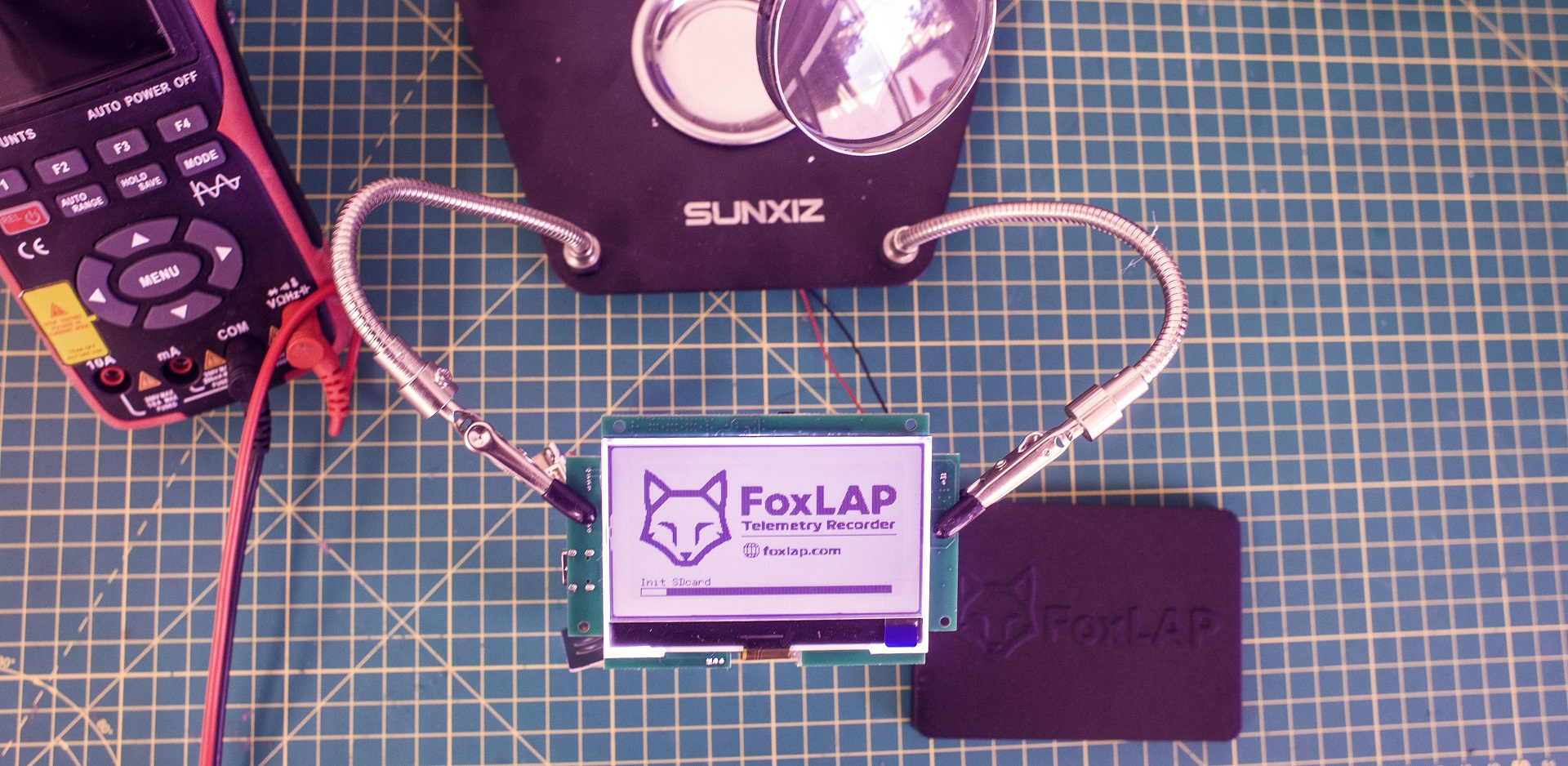
All the boards are fully tested before expedition.
2. Assembly guide

1- You must have printed the box enclosure – top and bottom part. (this is not the same model as the DIY version)

2- Inspect your print and make sure there are no defects. test the holes for the screws. You can enlarge the holes in the upper part of the box to make sure the screws fit properly.

3- Place the M8 30mm screw add regular glue at the top of the screw, then screw it.

4- Insert Hot glue inside remaining space where the M8 head is inserted (it’s very important to solidify this part, hot glue is mandatory)

You must have this. Now test your case assembly and try to screw in the M3 9mm. You need to be sure that the assembly of the box is correct and that you can close the box. once everything is ok you can continue.
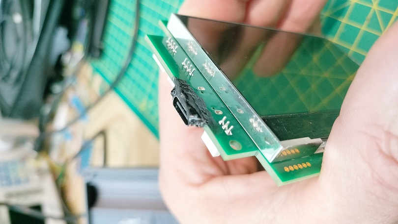
5- Take the PCB and add insulation paste to the bottom of the USB connector (be careful not to get this paste inside the connector)
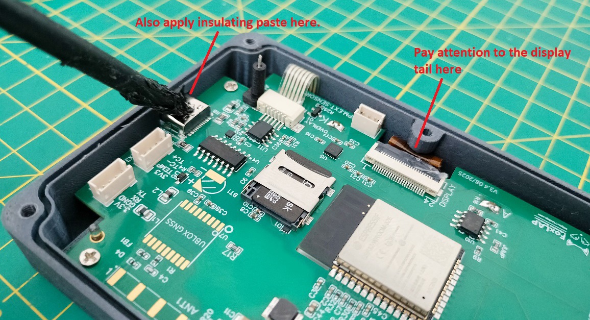
6- Put the PCB in the upper part of the box. You will have to start from the USB connector side.
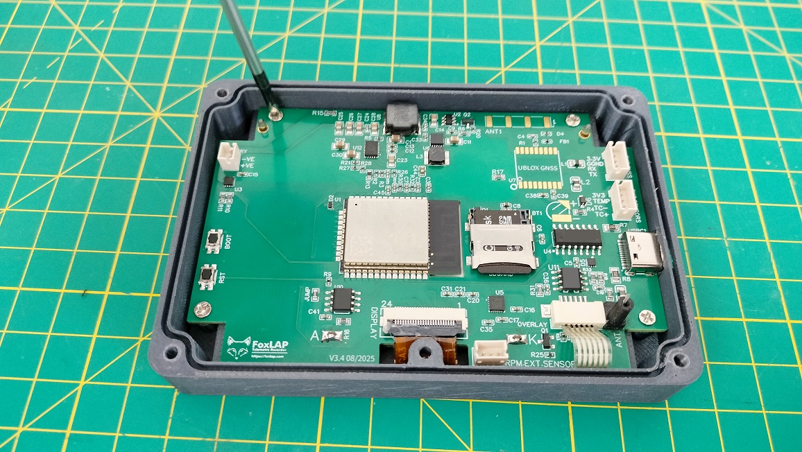
7- Secure the PCB with 4 M2 4mm screws

8- Flip it over. The PCB must be securely attached and must not move. don’t go pushing on it like crazy just to see if you can break the support. Of course you are capable. It just has to stand up to something reasonable.

9- Grab the overlay layer. Make sure your hands are washed and don’t put your fingers on the display or on the screen of the overlay

10- Add regular glue all around the screen. a thin layer only to fill in the irregularities of the 3D printing. Do not overflow onto the screen. otherwise it will be ugly.
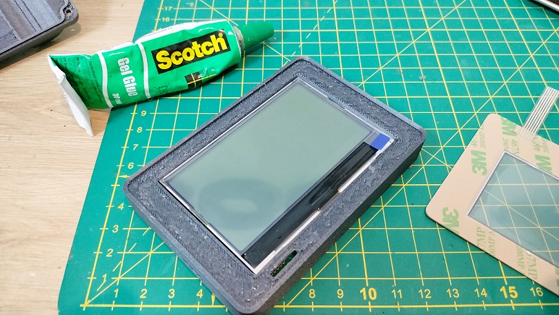
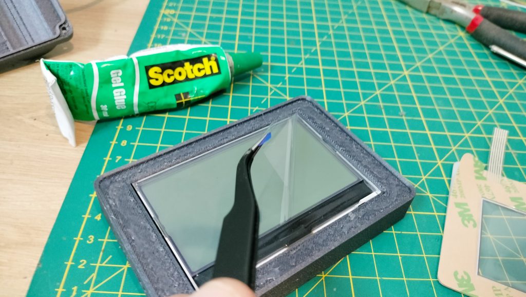
11- It’s time to be delicate. remove the protective film from the display. I said keep your fingers off!

12- remove the protective film from the adhesive side of the overlay and also remove the protective film from the transparent part. Did I already say don’t stick your fingers in?

13- insert the tail of the overlay in the hole (please no jokes). and stick the overlay on the box. make movements with your fingers to ensure perfect adhesion and adjust the positioning
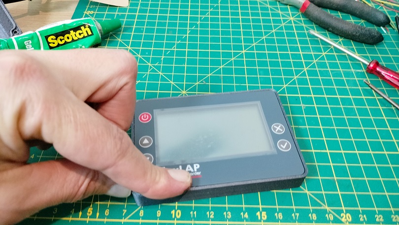
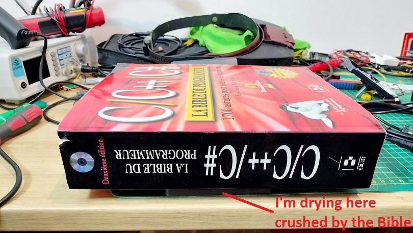
I generally place my Bible on top to let it dry for about 20 to 30 minutes. Oh no! not this bible, but the c/c++ programmer’s bible. the one that weighs 3 kilos. And yes I’m old, i learned with books in the 90s. High five if you’re old too !
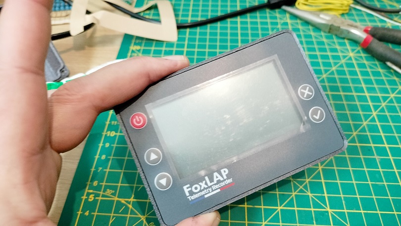
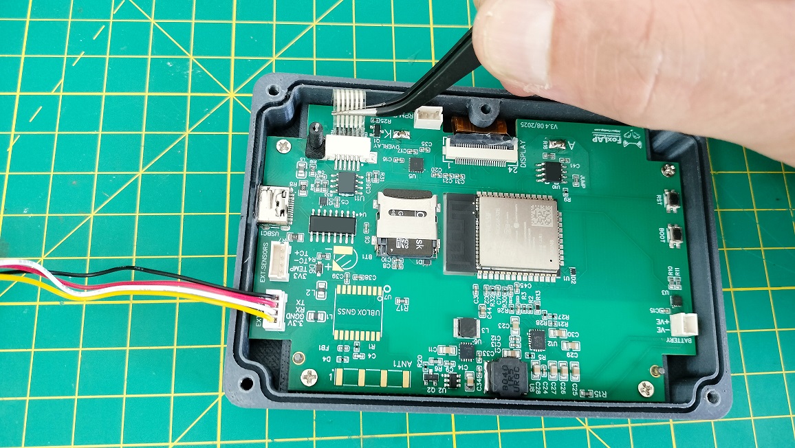
14- insert the overlay tail into the connector. can be hard, use this kind of tools to insert the tail
Well done, the upper part is finished. And all this without any soledring… too easy. But wait a little, maybe we’ll do some later… Soldering is something for the real men. and we’re real men, right?
There is still a protective film on the display. You will remove it only at the end – YOU WILL SEE THIS AS A REWARD FOR THE GOOD WORK CARRIED OUT.
15- Take now your 18650 battery. Use a spot welder to add Nickel strips to your 18650 battery. solder the cables (JST 2 pins cable). red for positive and black for GND obviously.
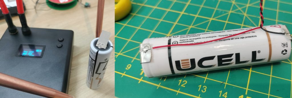
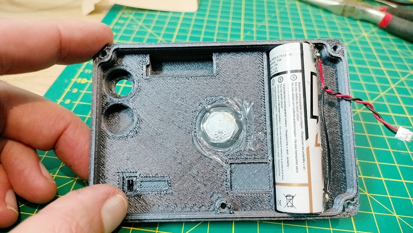
16- place your battery into the bottom part of the box. make sure to let enough length for the cable
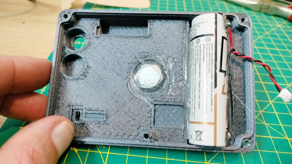
17- add hot glue to make sure it don’t move.
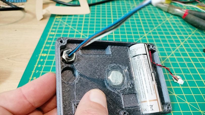
18- insert the M8 connector.
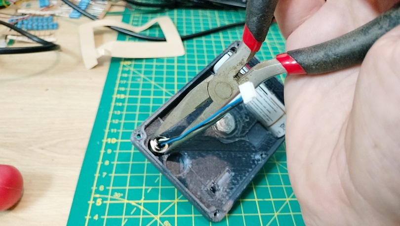
19- You may need to use a tool, depending on the print qualty, i t can be hard to make the first loop
TIP: Backfill the M8 connector cavity with hot glue to stiffen this area and add strain relief—especially for PLA prints. An M8 cable plugs in here, and a hard yank (shock, crash) could otherwise rip the connector out and damage the case. PETG-CF cases typically don’t need hot glue.
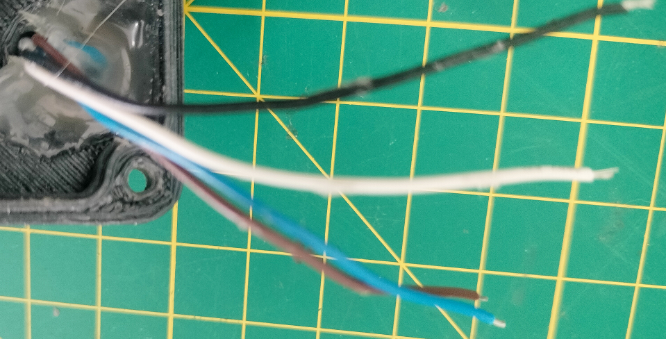
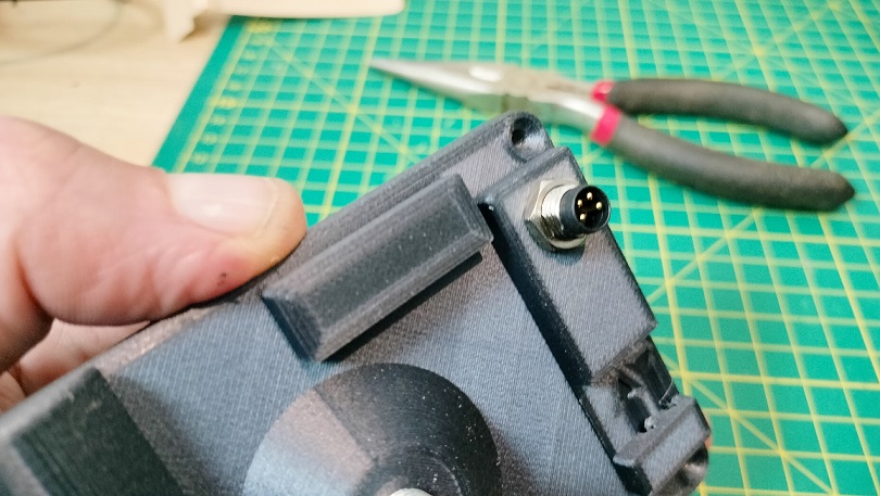
This dedicated board can host a GNSS receiver. You can order it with a pre-installed u-blox M10 chip and antenna (on request). In this guide, however, we’ll use the MatekSys M10Q module – the same one used in the DIY version.
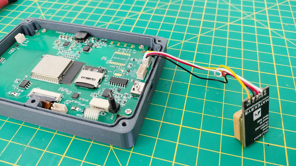
20- Take your GNSS module and the JST 4 pins cable. Plug the JST into the board and solder the cables 3V, GND, RX, TX to your module. once it is done, unplug the JST
IMPORTANT: RX on the board goes to RX on the GNSS module. And TX to TX. The dedicated board (since version 3.4) power the external GNSS module with 3V.
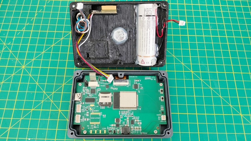
21- place the GNSS module into the place holder and add hot glue to keep it in place.
22- insert the SDCARD. FAT32 formated. Don’t use no name sdcards !
Sensors
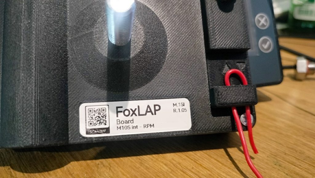
This board use an internal sensor to monitor RPM. You will only have to clip the RPM cable behind the box. On the main board, A metal rod is soldered to the ANT pin (comes already soldered). it will be the antenna to monitor RPM from the cable clipped behind the plastic case enclosure.
You will have another option with the RPM.EXT.SENSOR JST connector to use an external RPM circuit (3V, GND, RPM signal)
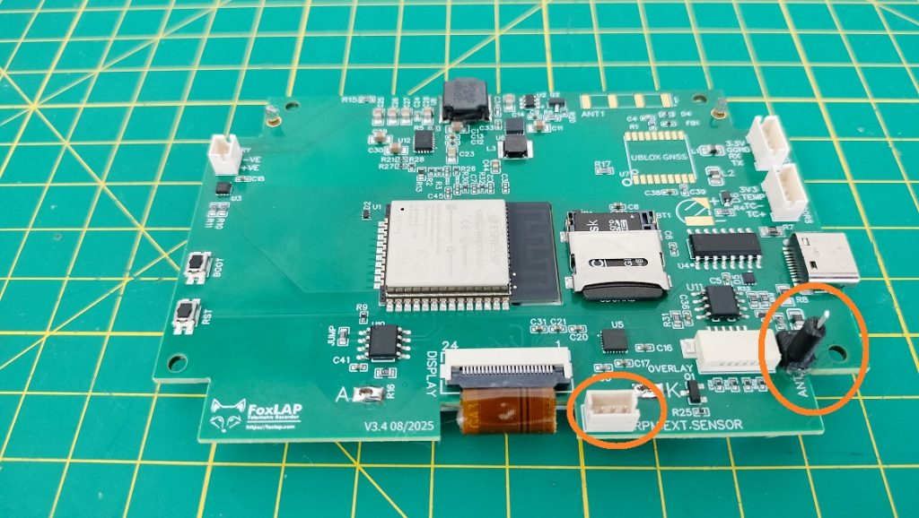
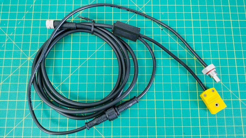
From the M8 connector, connect the cables as follow:
- BLUE -> 3V3 (JST 4 pins)
- BROWN -> TEMP (JST 4 pins)
- White -> TC- (JST 4 pins) (exhaut gaz temp)
- BLACK -> TC+ (JST 4 pins) (exhaut gaz temp)
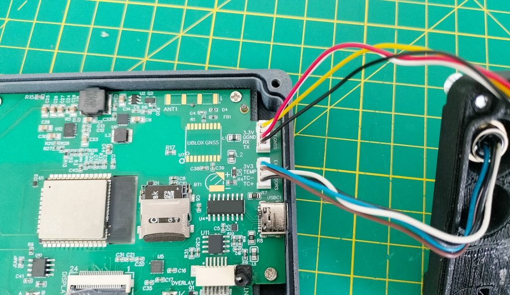
This dedicated board comes with his own cable allowing to plug an exhaust gaz probe and the water temperature probe. This cable goes to the M8 connector.
24- It’s time to close the box
3- First launch and configuration
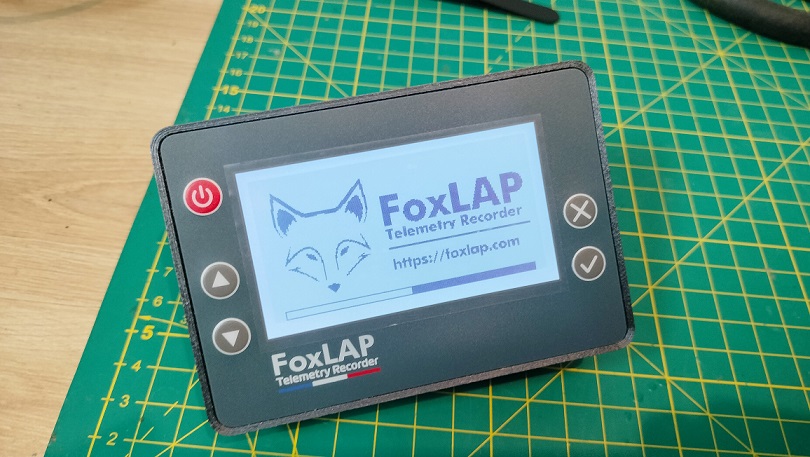
On the first launch, you must get this screen. If it is not already done, create a FoxLAP account here

You need to enter your name, select a password, etc. Some characters are not allowed, so be careful. You’ll need to enter this information into the device, and screen space is limited, so I had to make choices about which characters were allowed or not.
Only these characters are allowed at this time: 0-9, a-z, A-Z, ! # $ % & ‘ ( ) * + , – . @ : ; =
What you will need to enter on first launch is shown in this video. The device will must be able to connect to the internet, that’s why you will have to enter Wifi credentials. You can have some issues with passwords containing special characters not supported by the device, in that case, you can share your connection via your mobile creating a hotspot with a password containing characters supported by the device.
If the connection is unsuccessfull, shutdown the device and restart to retry
Once the connection is successfull, the device will retrieve the settings stored on your account available at that page https://foxlap.com/mydevice.php
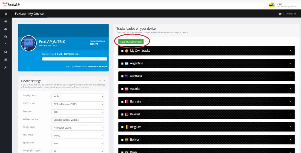
You will be able to change settings and also select/unselect available tracks on your device. Don’t select all tracks. Only select tracks from your country or the ones you will use. The more you select tracks, longer will be track detection. don’t forget to click on “Save Track selection” when you change selection.
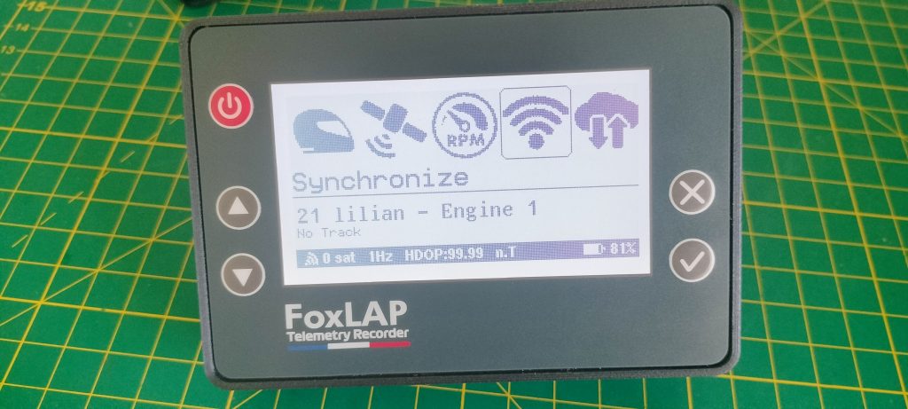
And, on the device, go to the “Synchronize” icon, then click on “Update track databse“.
What to do if your track is not available on the device?
I recommand to create your own track using the provided tool available here https://foxlap.com/track_creation.php
Once the track is created, go to https://foxlap.com/mydevice.php then select your newly created track in “My own tracks” category, then “Save selection”.
And also on the device: go to the “Synchronize” icon, then click on “Update track databse“.
4. Setup (using the RPM “internal sensor”)
Here you can see how to setup the foxlap device based on the dedicated baord with the internal RPM sensor. This will allow you get RPM (cable clip behind the box), water temperature and exhaust gaz temperature
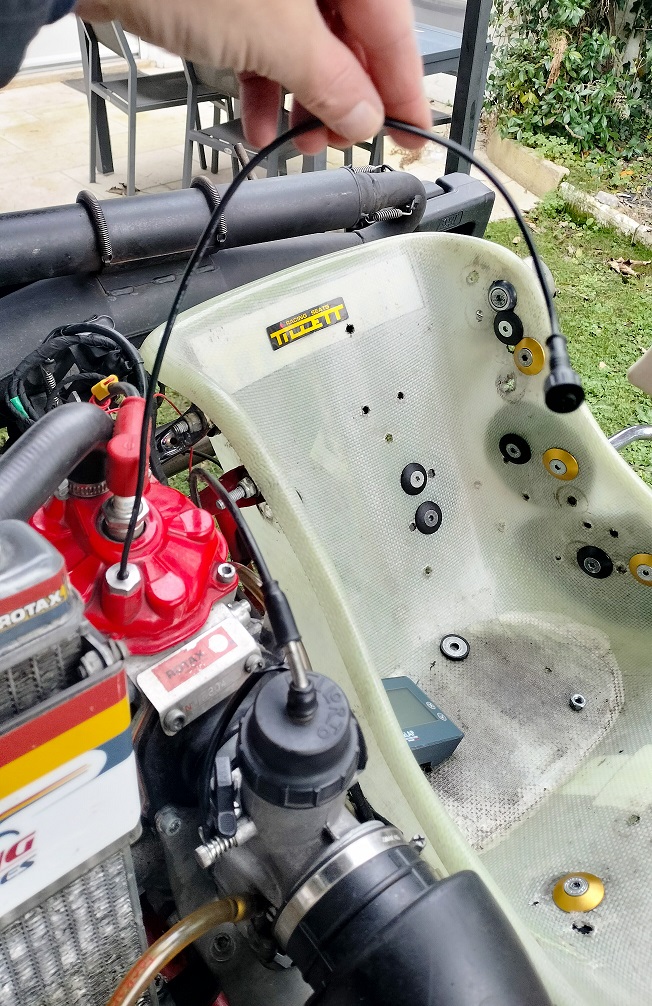
1- Install the water temperature probe.
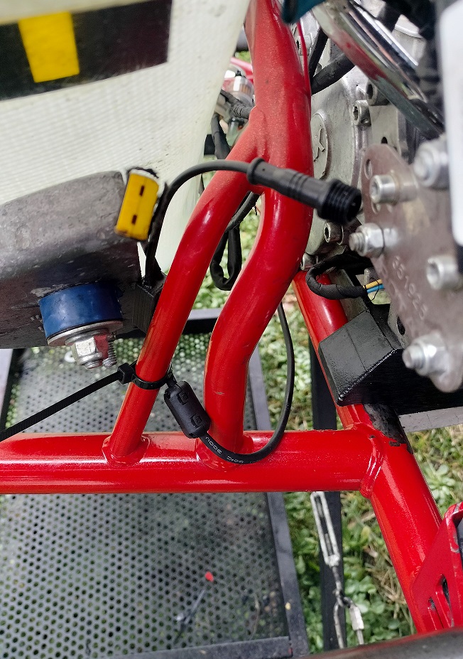
2- install the cable with the K-type connector for the exhaust gaz and the connector for the water temperature probe. Use zip ties to fix it on your gokart.
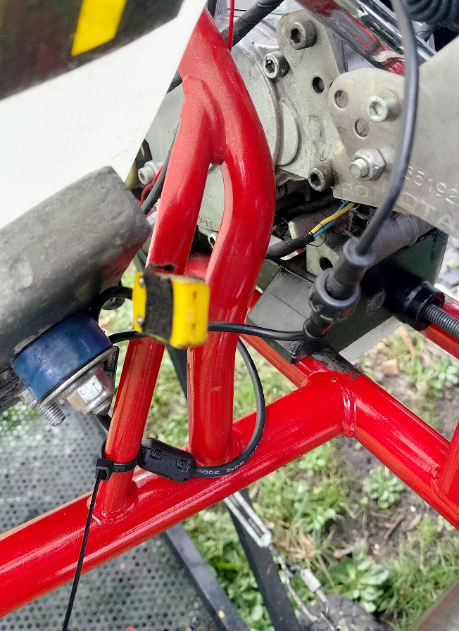
3- plug the water temperature probe
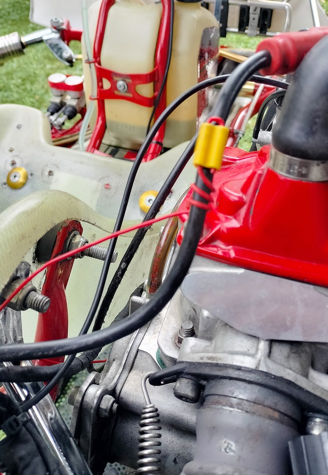
4- Install the RPM cable. The number of turns depends on the engine. Rotax engines typically need 2–4 turns -Don’t start with 20 – Begin with 3 turns and check whether the RPM reads correctly; then add one turn at a time until the signal is stable. Four-stroke engines usually need more turns.
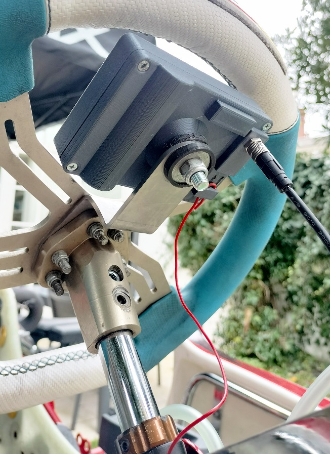
5- plug the external sensor cable to the fox lap device and clip the rpm cable in the housing provided at the back of the case
dedicated board Firmware
Version 1.70 – release date 2025/12/15
What’s new in version 1.70:
- Memory optimizations
- New race display introduced
- Various minor bug fixes
Install a new firmware on an exising and running device
Start your foxlap device. then select the menu “WiFi transfer” then “Start WiFi“. If you did not set a wifi password, do it on the device by selecting “WiFi transfer” -> “Set wifi password” (your password must be 8 characters length minimum.
Once it is done and your device is running in Wifi mode, you must see “Wifi Data Transfer” on the screen with the name of the created hotspot. (FoxLAP_xxxxxx). On your computer, connect the wifi to this hotspot (be careful, passwords are case sensitive)
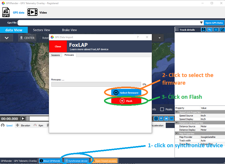
Then open the software GPXRender (available on this website). Click on “synchronize device”. If your are connected to the device, a window will popup. Go to the “Firmware” tab, then select the new firmware file and then click on “Flash”. You are now able to flash device without the need of dismounting it

What are the optimal GNSS settings integrated in the new software version 1.54?
current version is 1.58 – update your device.
it depends on your location… but for europe:
GNSS mode: i don’t advise to choose all constellations (lot of messages and frequency limited). GPS + Glonass + SBAS works well. i choose GPS+Galileo+SBAS in more urban environment.
GNSS coordinate projection activated: it avoids to miss a gate if you get a very poor signal (i don’t know, inside a forest for example)
GNSS dynamic model: Automotive of course by default. you can test Airborne 2G or 4G for very fast engines with brutal direction change. (KZ gokart can test this mode)
GNSS SBAS: select your location
ETA on dedicated boards? Love my DIY!