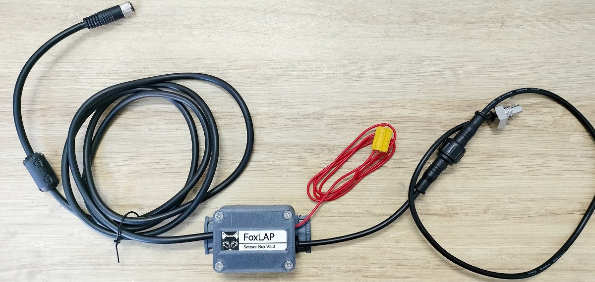
I’m publishing 2 versions of external sensors. the first version is easier for the FOXLAP DIY version and the second version is the best option for the dedicated board device.
The first version is called “external sensor box” (and i’m starting with this version). the second version will be called “internal sensors” (even if obviously the probes are not inside the box, but i just had to give them a name)
Why the “external sensor box” is better for the DIY device? because there are already so much cables and little boards inside the device that it became tricky to add even a little board inside. i made it and it works but there is no added value to make the device more complicated inside. the “external sensor box” does the job as expected and it is easier to assemble.
1- External sensor box
This tutorial will explain how to build the external sensor box to monitor RPM and water temperature. This sensor sensor box will be connected to the FoxLAP device (compatible with both DIY version and dedicted board) via a 4wires cable with an M8 connector.
1.1 – Print the model
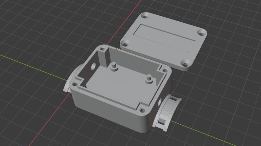
- STL files were created using Blender.
- 3D Printer: Creality CR10s PRO.
- Slicer: I used Cura to slice the 3D models
- 3D filament: i used the 1.75mm ZIRO Filament PLA with carbon fiber. Amazon link: https://www.amazon.com/dp/B01IICFS4Y/
- Print settings: 0.4mm nozzle, Standard quality (0.2mm), 40% infill, Support (zig zag support)
- Print Speed: Usually I set the speed to 60% of the maximum speed the printer can achieve. Because I saw that the more I increase the speed, the more faulty prints I get.
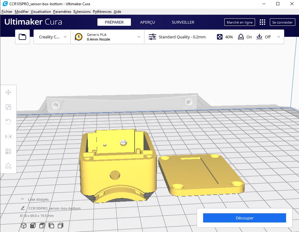
The zip contains the box and the RPM clipper.
1.2 – What you will need
FoxLAP – External sensor pack
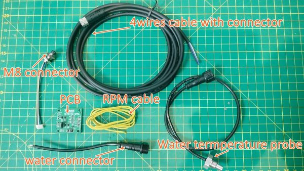
FoxLAP – External sensor pack. Everything needed to Monitor RPM and water temperature. The PCB will be connected to the FoxLAP device (compatible with both DIY version and dedicated board version) via a 4wires cable with an M8 connector. In this picture you see the content of the external sensor pack. Probes and connectors were custom made to be mounted on goKart engines such as Rotax (J125, Max, Max Evo) More info
Get informed when stock available
In this picture you see the content of the external sensor pack. I made a package including what you will need. probes and connectors were custom made to be mounted on karting engines such as the Rotax. It includes:
- 1 cable (4wires) with a 4 pin connector (2meters, you can adapt length to your need)
- 1 M8 connector (will be mounted at the bottom of the FoxLAP device)
- 1 PCB
- 1 RPM cable
- 1 water temperature probe with his water proof connector
- 1 Clip-On Ferrite Ring Noise Suppressor
- 4 M3 9mm screws
External Sensor pack available here: https://foxlap.com/tutorials/product/foxlap-external-sensor-pack/
or contact me here, I have also few dedicated boards available
1.3 – Assembly guide
Put the PCB inside the printed box. H2 on the side of the box where there is only 1 hole
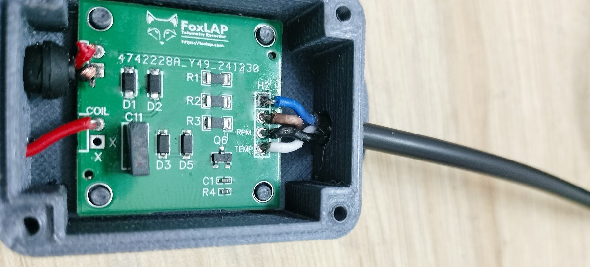
Adapt the length of the main cable (the one with the 4-pin connector) to what you need on your gokart (or bike or whatever). Usually a good length is between 140cm and 150cm. Keep in mind that you will have to install it on your gokart/bike. So please take a look at the setup guide before
Insert your 4-pin cable inside the hole and solder the 4 pins. Keep the color rules as mentionned here because this cable must be connected to the foxlap device (and we don’t want any nasty surprises with incorrect wiring)
blue ->+3V
brown ->GND
black ->RPM
white ->TEMP
You will need to solder the wires inside the box so be carefull. I use solder paste to make this task easier (I’m just sharing with you what is easiest for me – but maybe you have your own tips and habits)
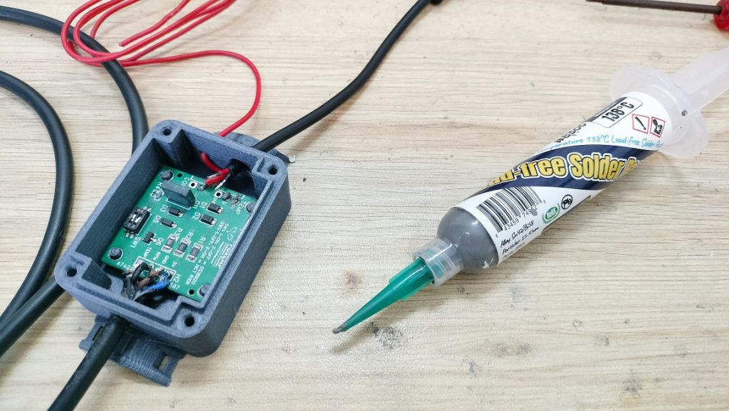
Solder the RPM cable to the COIL pin and the 2 wires water temperature cable to “D” and “3V” pin (no matter wich cable goes to D or 3V)
You must have now something like that:
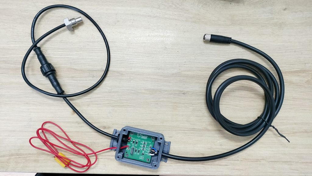
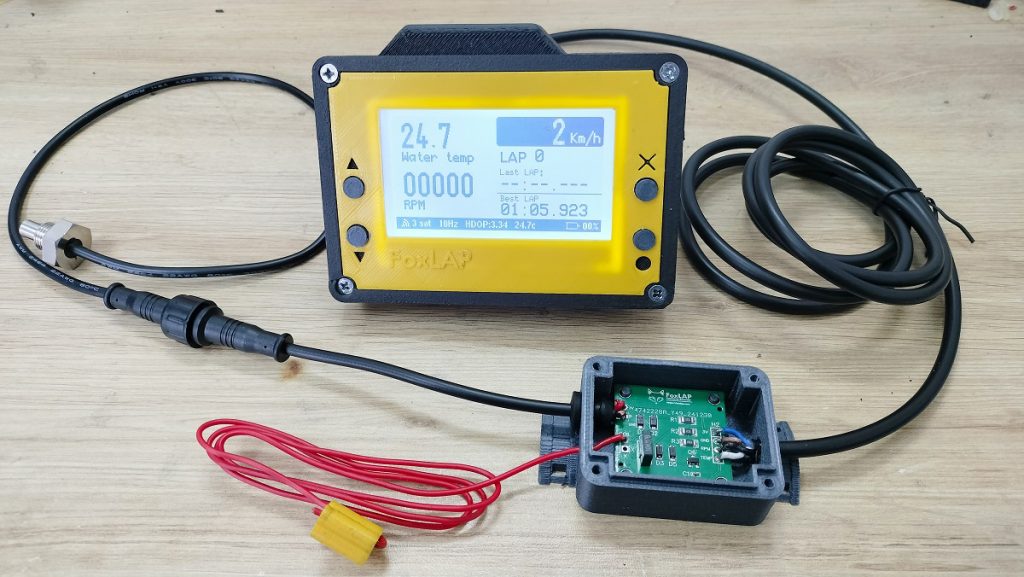
Before closing the sensor box, make sure it works by pluging it to your foxlap device (if you made the version able to host external sensors – otherwise go to the foxlap DIY tutorial in order to get it done)
Once your test is OK, put hot glue (or isolation paste) inside the box to close the cables holes to prevent water to enter.
And then finally close the box with the 4 M3 screws
IMPORTANT in case of use with the DIY version
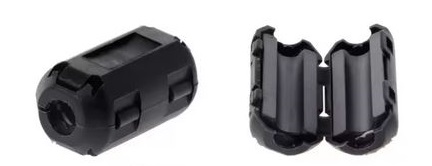
Particularly in case of use with th DIY version, you must add a Clip-On Ferrite Ring Noise Suppressor on the 4pins cable. you can find it here https://www.aliexpress.com/item/1005007138649892.html for example if you don’t already have it.
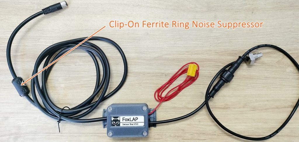
And it’s done. now we have to install it on the gokart
2 – Setup
It’s not something difficult, if you are at this stage now, the hardest part has been done.
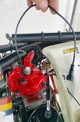
Install the water temperature probe on your engine.
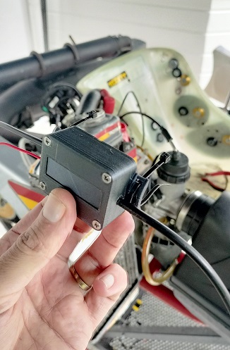
prepare Zip ties to install the box
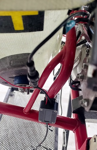
This is where i install the sensor box. So it’s easy to access to remove the water temperature probe when you change the engine. Add other zip ties to install the cables properly
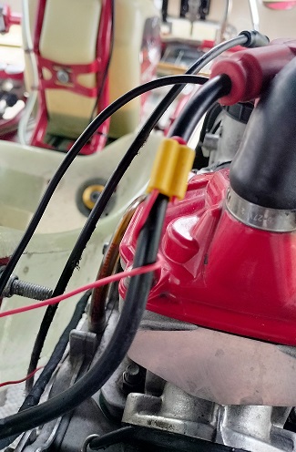
clip the rpm cable
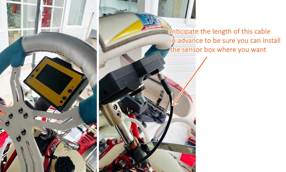
And now it’s time to see it in action. (no error for the water temperature sensor, it was close to 0°c when i recorded this video )
Ciao
i’ve received your external sensors box, to use in a DIY version. I’ve done all works (created box , and then solder the M8 connector to ESP inside Foxlap DIY). Everything seems to be ok but when i connect external sensor to foxlap in Water temperature sensor report 0°. RPM is not connected on the engine so it’s normale that also ti reports 0 RPM. Is it normal? (i’m asking this because in picture on tutorial water temperature , in that case ambient temperature, is sdisplayed).
I have checked that all solder are ok with a tester and there are ok. Also 3,3 v is present in the sensor box (blue and brown wires tested with tester,) and also at the Water temperature sensor. I’ve also check continuity of all wires from ESP to m8 4 pin connector in back part of Foxlap and everything is ok.
Could you please give me some suggestion?
Thanks very much in advance.
Ps Just another question. When dedicated board will be available again?
Ciao
Andrea
HI Andrea,
It should indicate the ambiant temperature and not 0°c. double check wiring
And also make sure you have the lastest version of the firmware installed on your device.
Ciao
Thanx for your reply. I have checked wiring several times and already updated firmware some months ago. Add soon as I come back from track , (today I’m testing it on track and also rpm are not shown) I will update firmware another time and re check wiring. Then I wrote you back.
Thanks for your support
Ciao
i’ve updated to latest firmware and everything works great…on table of my kitchen ;P… i will test asap on track. Thanks a lot
Have a nice night
Andrea
Hi, what kind of temperature sensor resistance are you using? I tried connecting several sensors. And whichever one I use, immediately after connecting, the temperature rises to 104.9 degrees. I even tried to put a regular resistor with a nominal value from 200 ohms to 100K, but the result is still the same. Why is that?